Tamiya TRF419XR Build
For the TRF419XR, Tamiya has at least for now decided on the rather strange strategy of selling it as a full chassis kit only on the domestic Japan market, while export markets gets the TRF419XR Conversion Set.
Therefore, we take a look at the 42317 TRF419XR Conversion Set in this build. Luckily, I have a lightly used TRF419X in good condition, so this car will be the basis for this build. Please note that the conversion set can only be used to upgrade the TRF419X and TRF419X WS versions. It is not intended for the older TRF419, which has many differences to the X versions.
This build will obviously also give a good picture of the 42316 TRF419XR Chassis Kit, as the finished car will be the same, with the only parts not included in the conversion but in the car kit being the optional taller damper towers for the older longer TRF dampers, and the heavy battery holders mainly intended for use with light Tamiya stick packs.
According to Tamiya, this latest evolution of the TRF419 focuses on cornering speed and steering response. Let’s see how they have strived to acheive that then!
…
The conversion set comes in this flat box in typical TRF styling. It is surprisingly light, so no big shipping fees on this product!
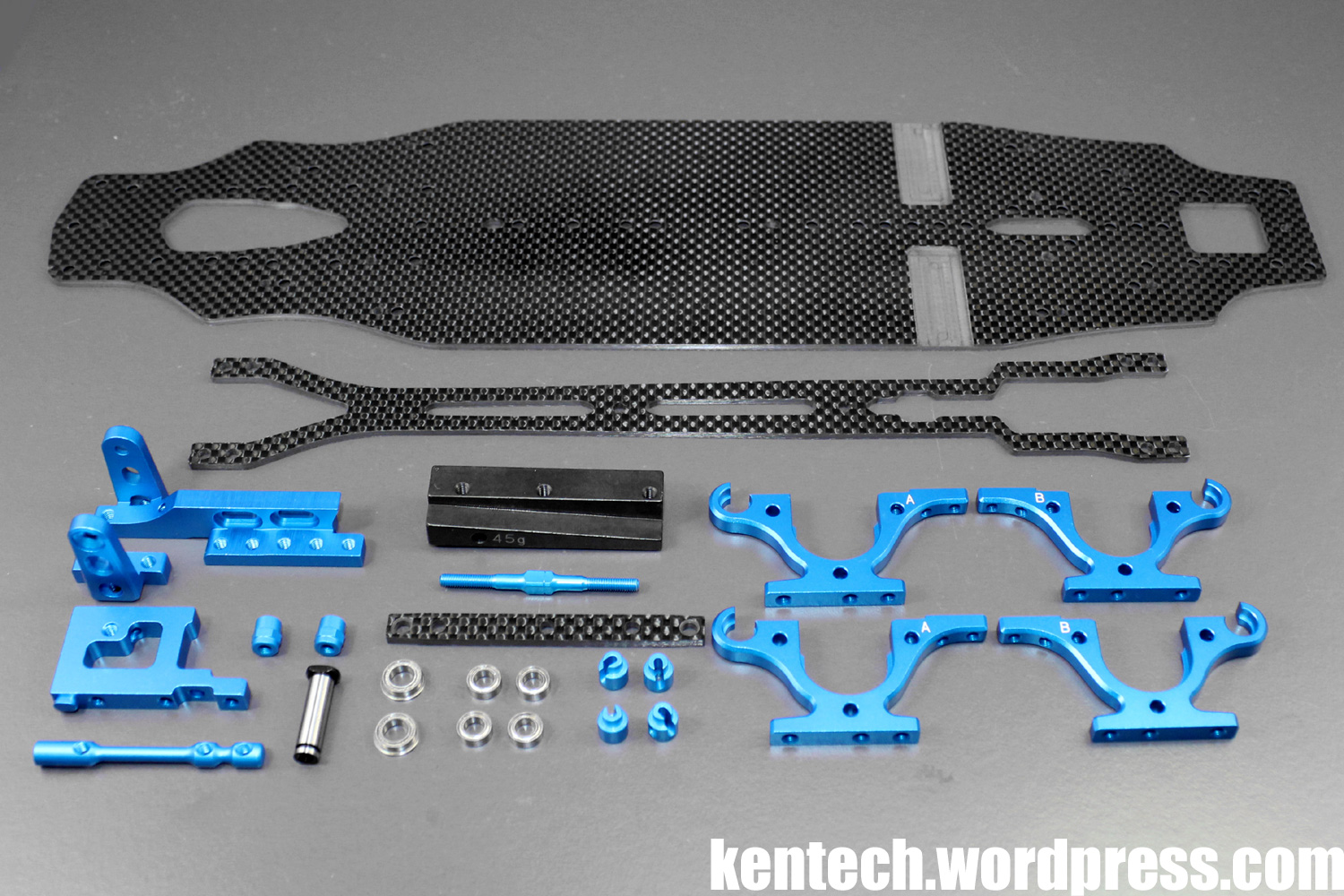
Next up you see a picture of the actual contents of the TRF419XR Conversion Set.
Obviously there is a new main chassis, a new upper deck, and new lower bulkheads. The left and right motor mounts are new, with a nice aluminium fan mount that attaches to the motor mount also included. The inner part of the servo mount is also new.
There is a new heavy 45g center ballast weight, as well as part for the new center pitch stiffener, with options of a carbon brace and a turnbuckle link all included. Finally there is the new 5mm center shaft with new 5x8mm flanged bearings, while finally in the picture you also see the 4x7mm bearings and rod stoppers for the now bearing supported roll-bars.
Missing from the picture but included in the set is various screws, shims and nuts, as well as ball cups for the pitch stiffener. There is an 8-page manual, with more setup tips than normal for Tamiya, and a new TRF419XR sticker set. These can be seen in the previous post here on Blog Kentech.
First, let’s take a look at the small differences between the original TRF419X lower deck and the new TRF419XR lower deck.
As you can see from the picture, they are fairly similar, but there are quite a few small changes.
The 419XR lower deck is 2.25mm thick, while the 419X is 2.15mm, so it is 0.1mm thicker. Both are the same width at 85mm. The outline of the chassis is very similar, but the new XR chassis is around 1mm wider per side, roughly between the front arm downstop screw extension and until it reaches it maximum width in front of the servo/battery mount.
As can be clearly seen, the cutouts under the diff/spool are much larger and now fully symmetrical. Apart from this, the changes are that there are extra holes for the new motor mount, servo mount, and center weight added, as well as some new holes on the centerline behind the motor mount. The cutouts for allowing access to the pinion gear from the underside has been deleted.
The XR chassis is 1g heavier at 70g.

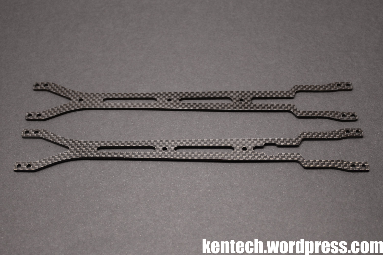
The upper deck is again slightly revised. The front “V” cutout is slightly wider and longer by around 4mm. There are other very slight differences on the cutouts as well, but perhaps the most noticeable change is the larger cutout towards the rear to allow access to the pinion after the access holes to the lower deck were deleted.
Both the X and XR upper decks are 2.0mm thick and of a similar type of carbon fibre.
Below you see a comparison between the original 419X lower bulkheads, and the new 419XR bulkheads. The only real change is the addition of the bearing holders for the new bearing supported roll-bars. I left the old roll-bar holders to the old bulkheads for reference. Weight is basically exactly the same.
As you can see, the three screw holes for fastening the bulkheads to the chassis has been retained, with corresponding holes also on the XR lower deck. This gives you the option of 2 screws in different locations, or 3 screws, all to give more flex adjustability.
Bulkheads mounted to the chassis.

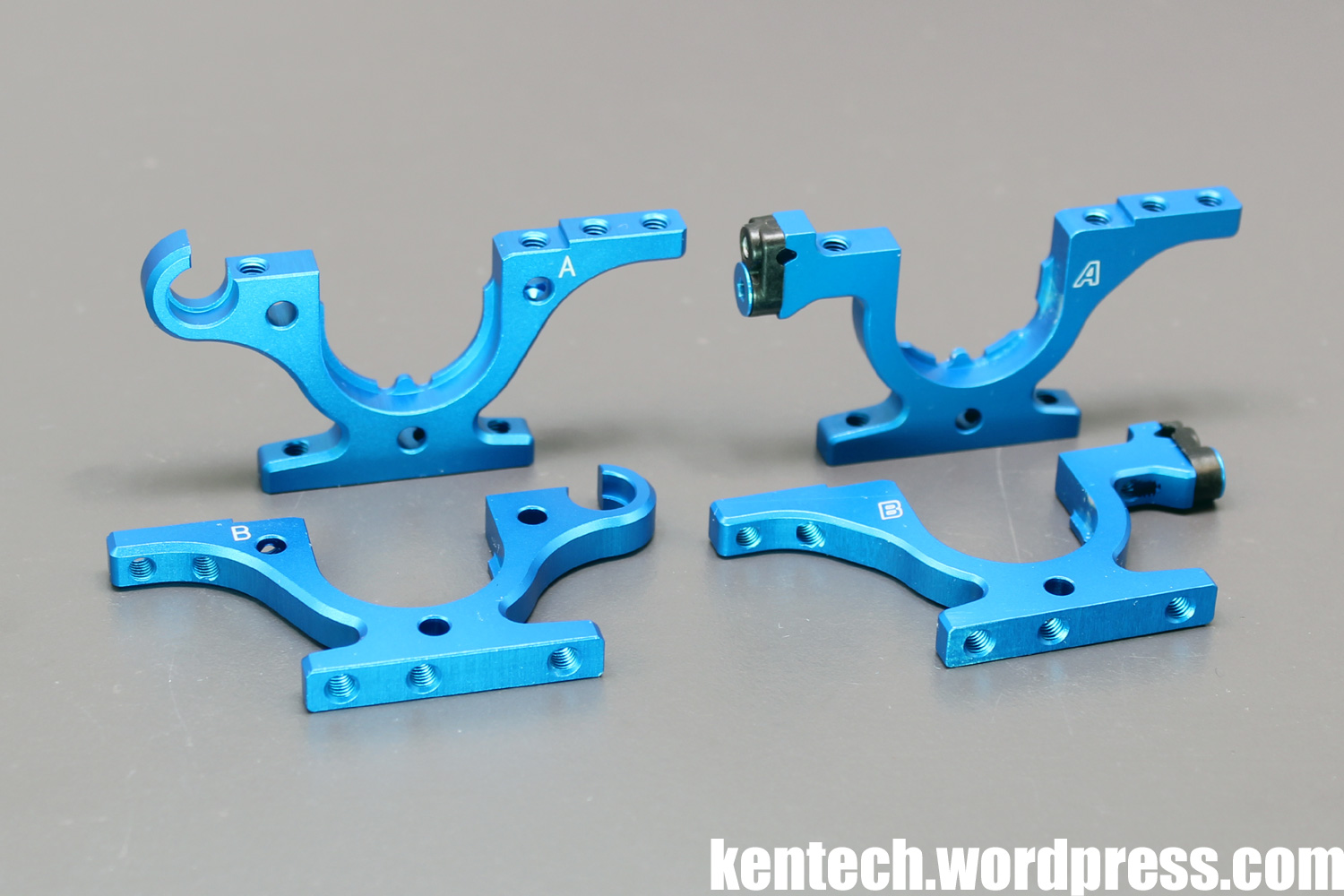
Again, a side by side view of the 419X and 419XR left and right motor mounts. The big difference is that the XR mount has three more holes further back on the center line mounting, giving you even more flex tuning options.
The shape of the motor mount is also slightly changed at the front, as well as at the rear with the a hole for the included motor fan mount added. The right side mount has been redesigned to have the same cutouts, while both have also been modified to accept the new larger M3 center shaft screws.
The initial setup uses screws in the same location as on the 419X, with optional holes further towards the rear.
Probably my favourite picture of this build so far! 🙂
Another side by side with the new and old inner servo mount, the only difference being the extension rearwards, with this hole also used for the new center pitch stiffener.

Different options for the center pitch stiffener are included.
This is the default setup, with the 2.5mm thick carbon fibre stiffener used with the “semi” countersunk holes and countersunk screws. Steel screws are included, I used Tamiya alu screws.
You can also turn the carbon stiffener over and use normal round-head screws, for slightly less stiffness.
A further option described in the manual, with parts included in the kit, is the following setup.
This option uses 3x20mm screws that go through the chassis, servo and motor mounts as well as the stiffener posts and the carbon stiffener. Then 0.7mm spacers are added on top while everything is secured by M3 nuts.
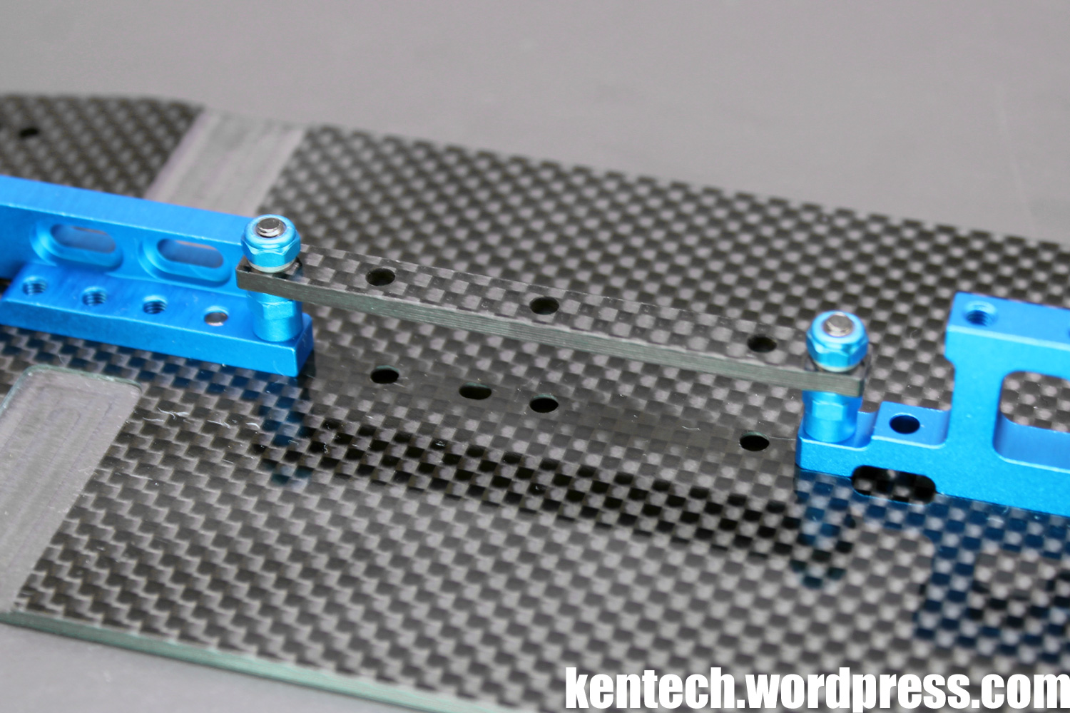
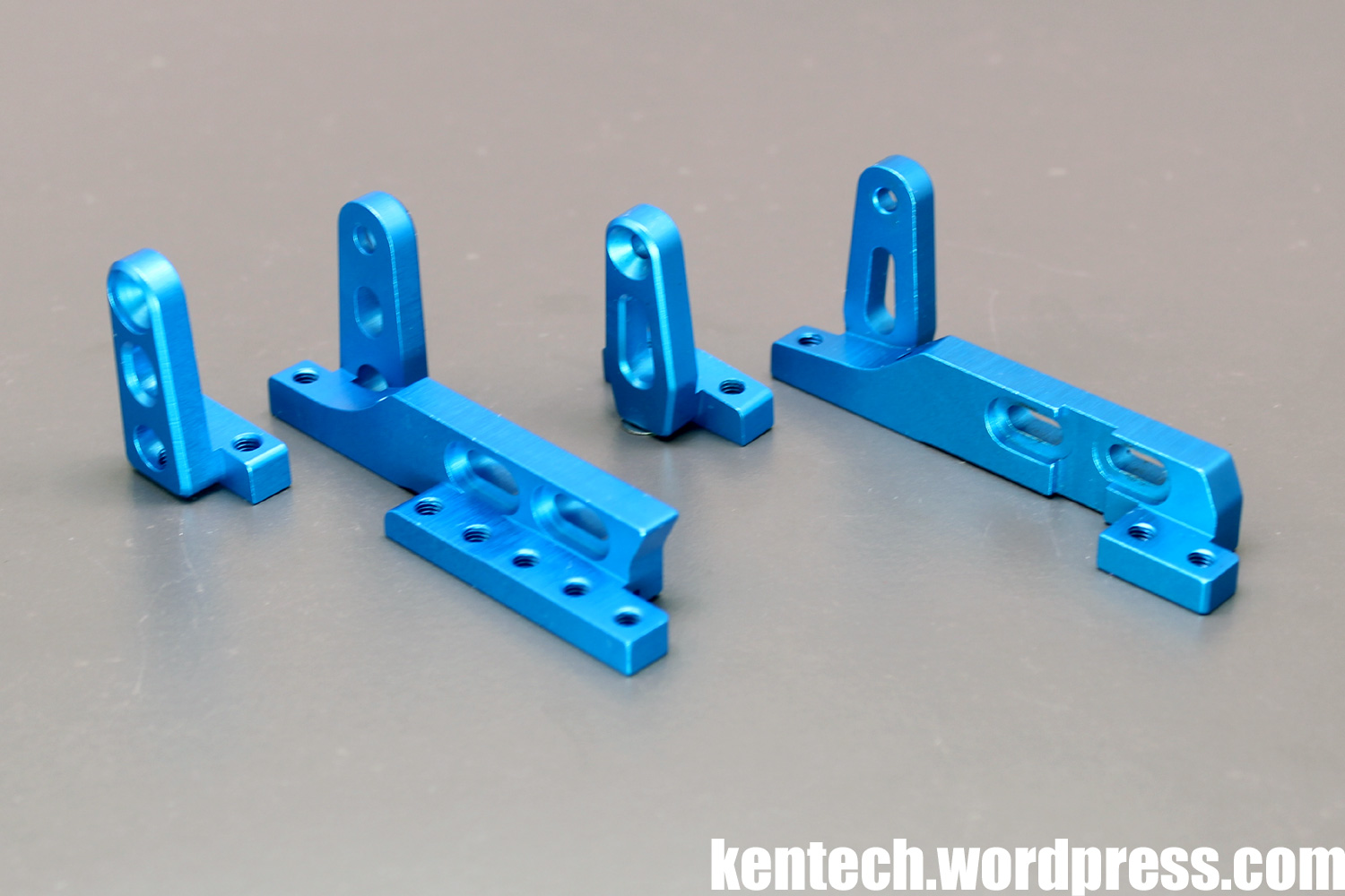
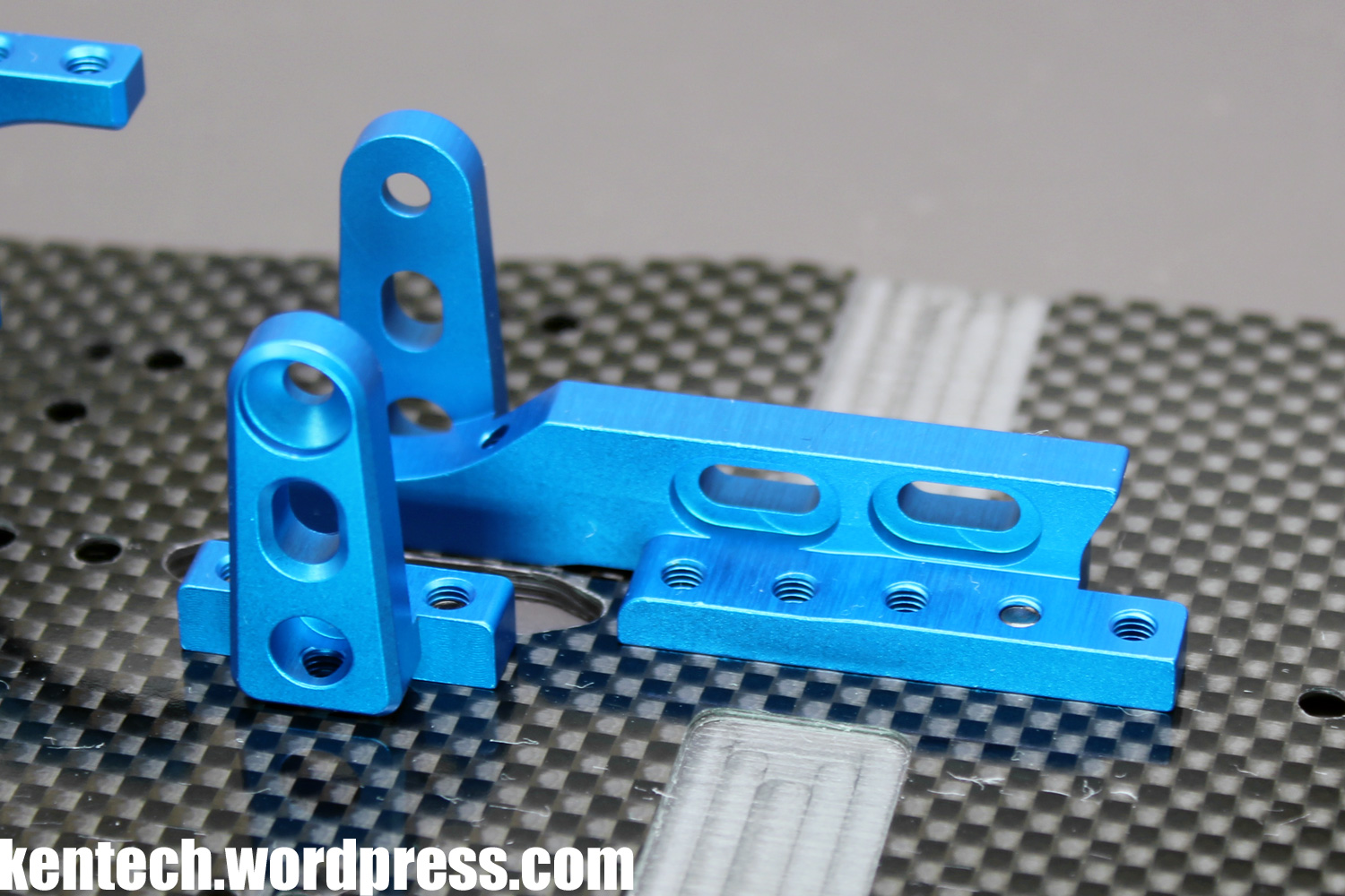
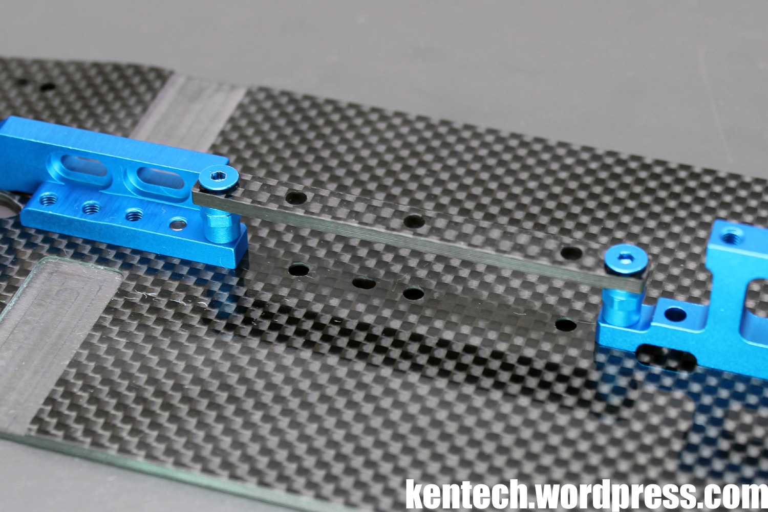
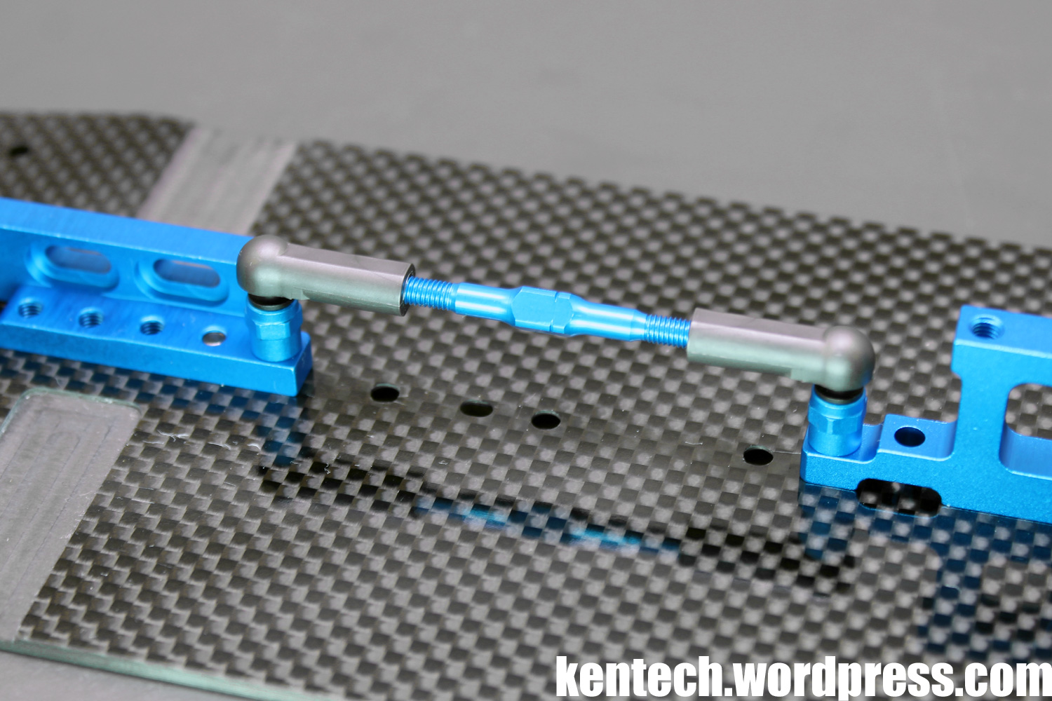
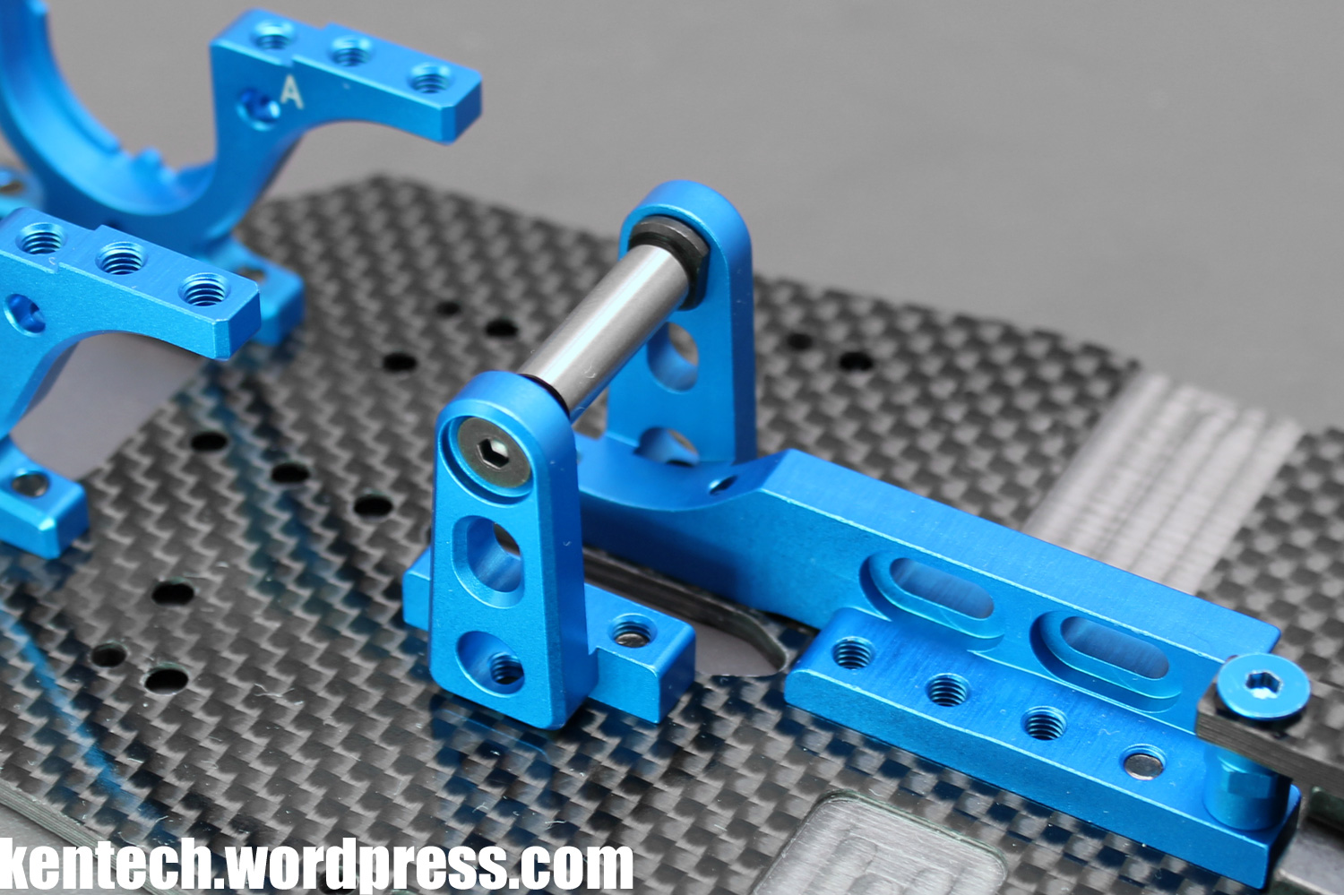
The final option incuded is this turnbuckle and ball connector setup, being the most flexible option of center stiffeners.
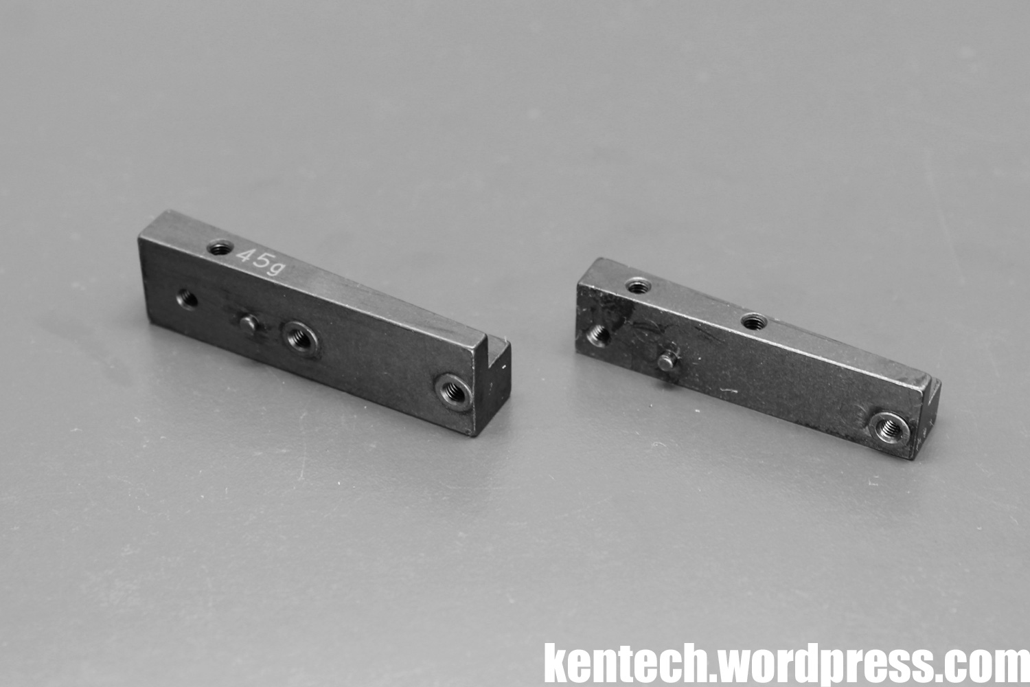
The old 30g center ballast weight from the X, is replaced with this 45g piece on the XR. Again, more options have been added when it comes to mounting it to the chassis, even further increasing setup possibilities.
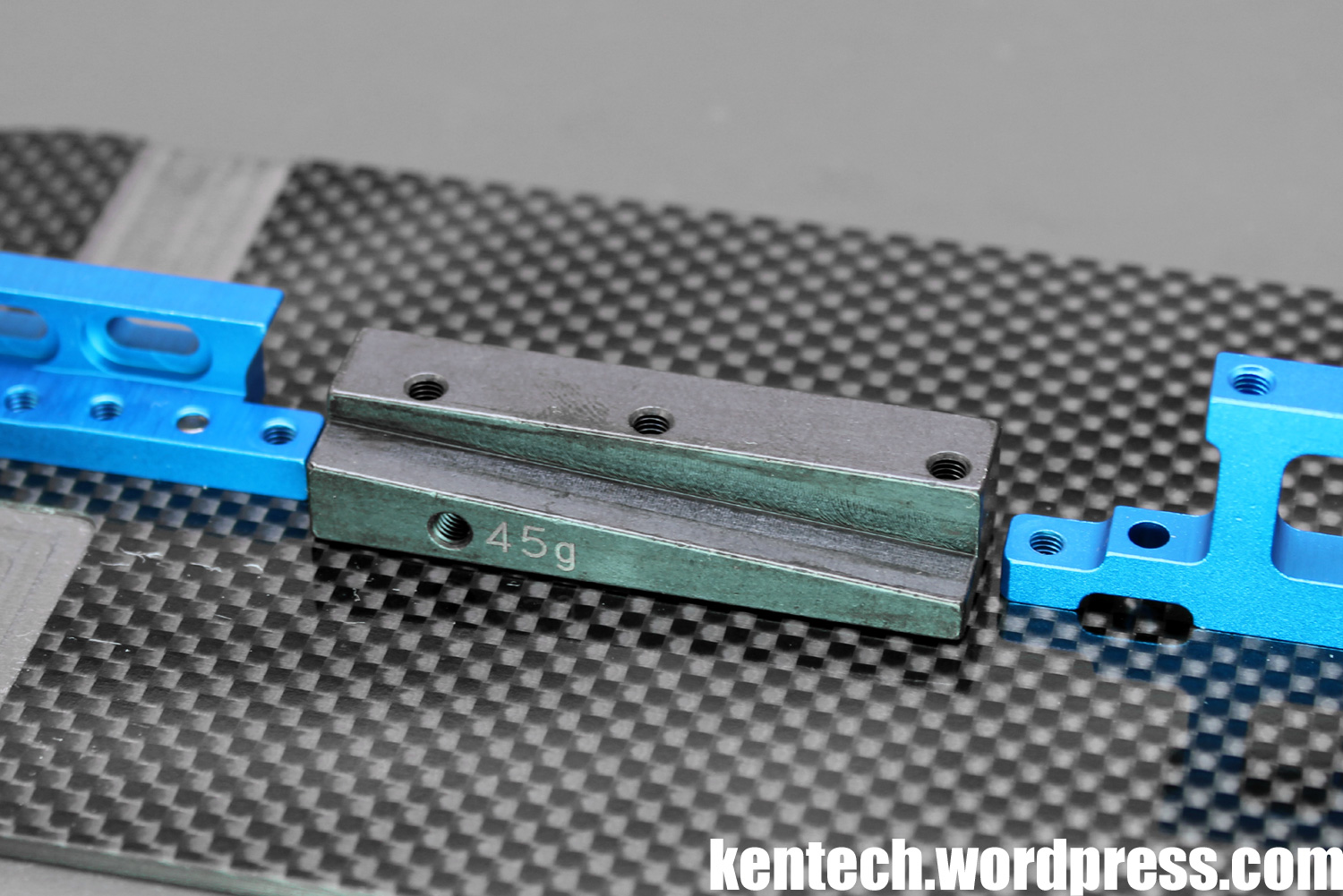
Here mounted to the chassis, with the cutout for the belt visible.
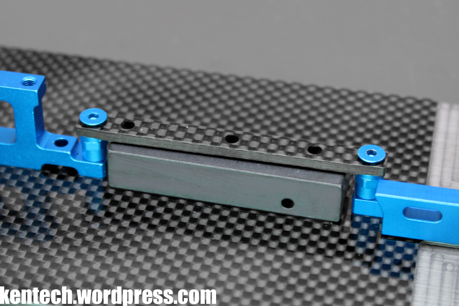
Together with the center pitch stiffener, the setup looks like this.
That Tamiya includes these parts with the kit, and not only as option parts, has to be seen as a big positive.
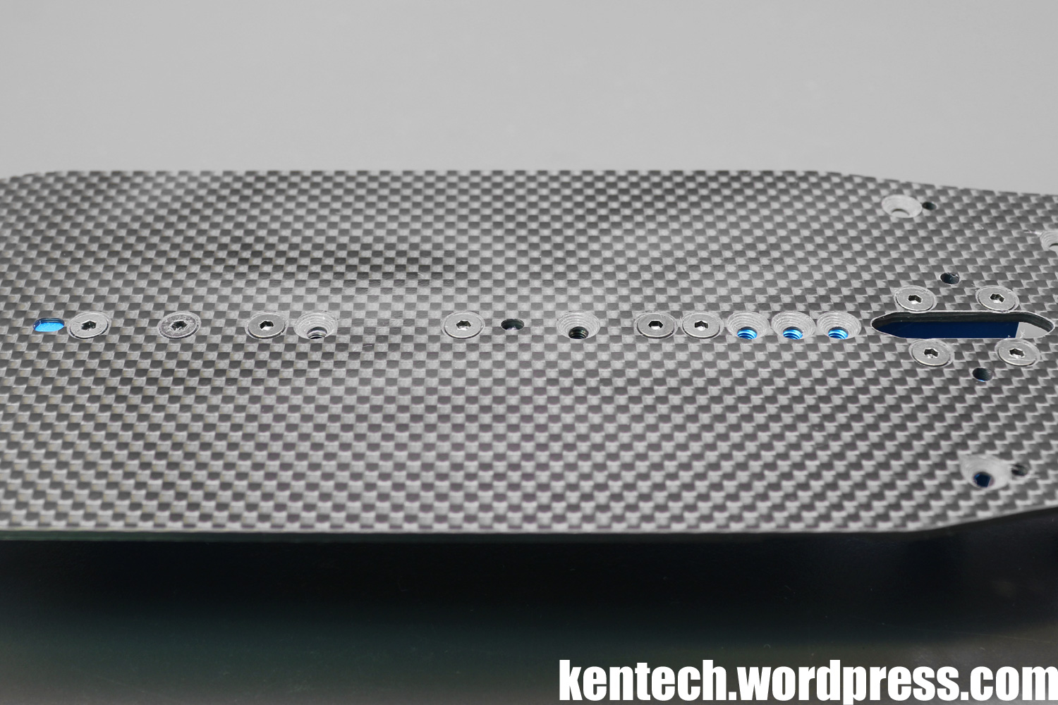
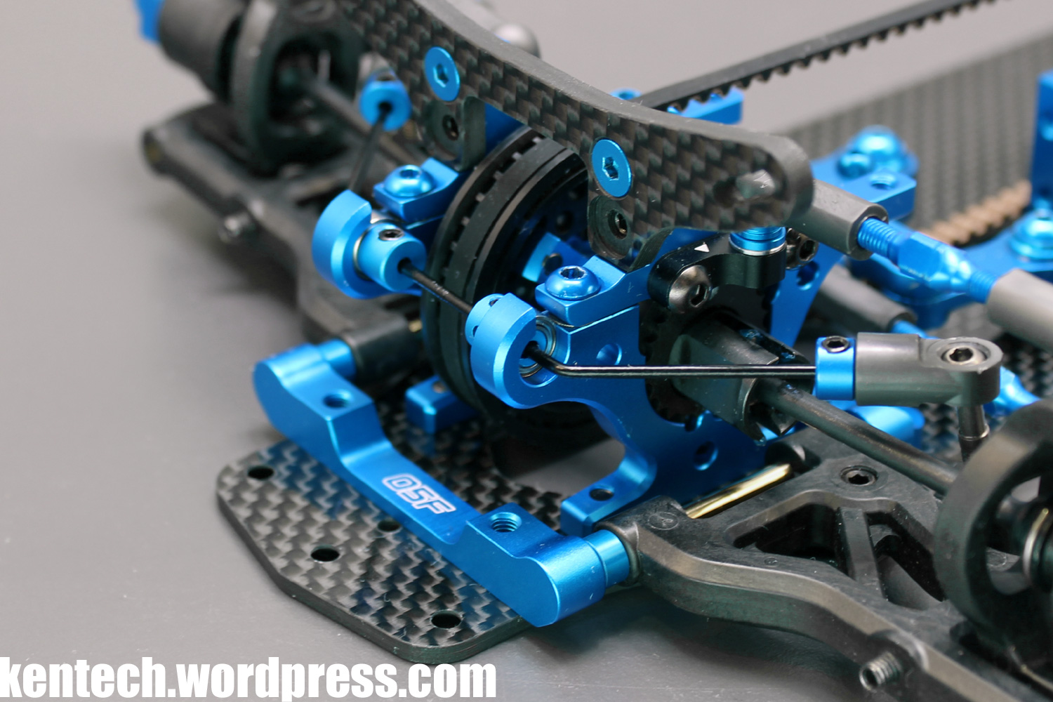
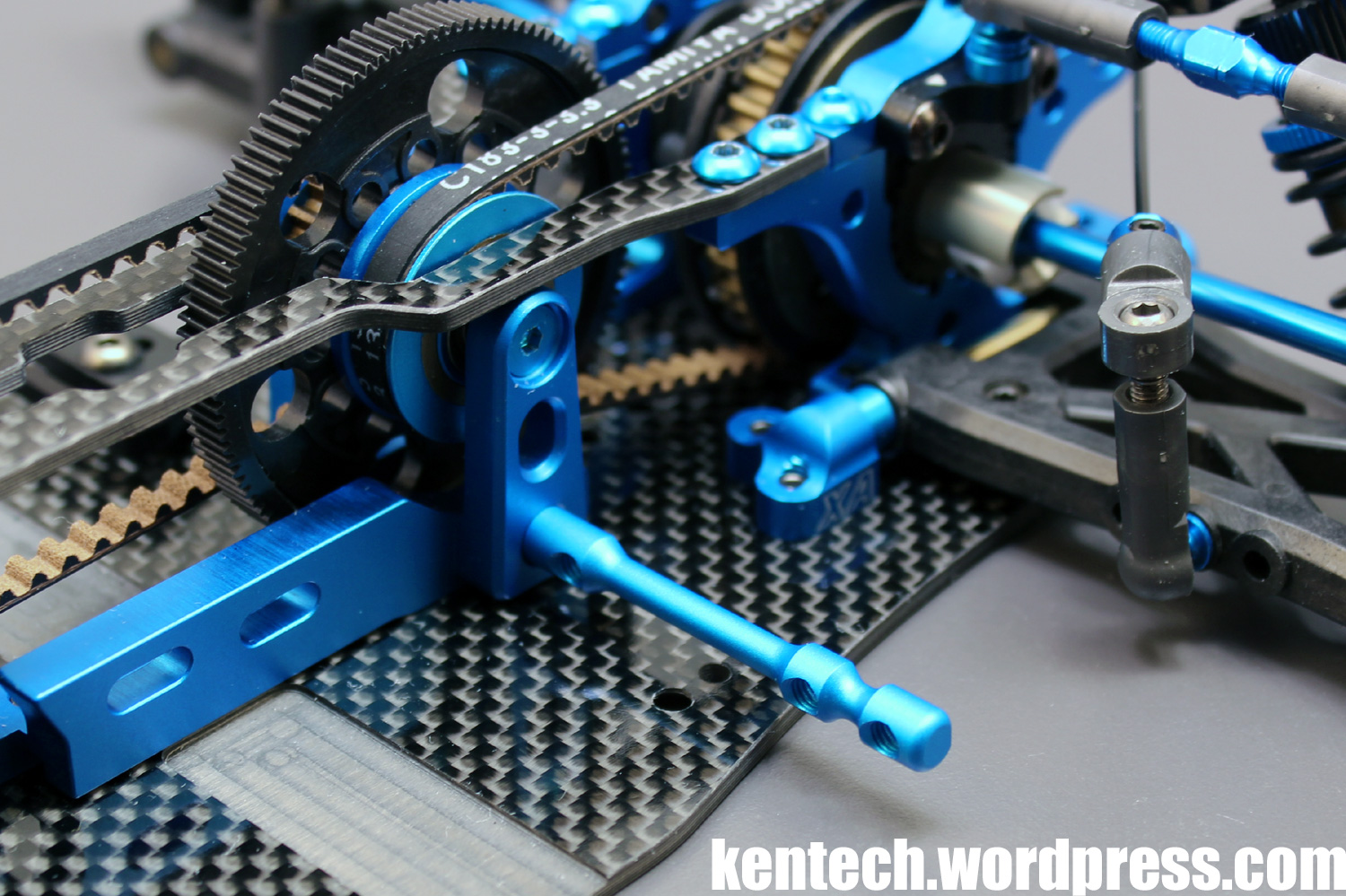
The multiple holes on the chassis center line that can be used for flex adjustmens with the motor mount, center ballast weight, and center stiffener.
The new center shaft is 5mm thick instead of the previous 4mm, and uses flanged 5x8mm bearings inside the 20T pulleys, in place of the previous 4x8mm flanged bearings. This change also allows M3 screws to be used instead of the fragile M2.6 screws used previously.
Next I will continue assembling the whole car, but I chose to present the new parts in this way first, as this is a conversion kit and not a whole car kit.
I will go over the rest of the car quite quickly with just a few pictures, as most of it is basically about adding the parts from the TRF419X, which I built already in May 2016. I will focus mostly on the rest of the new 419XR parts in the remaining pictures.
As you can see I assembled the car with a diff using the 42310 37T Aluminum Differential Pulley, as I have had one lying around but never tested.
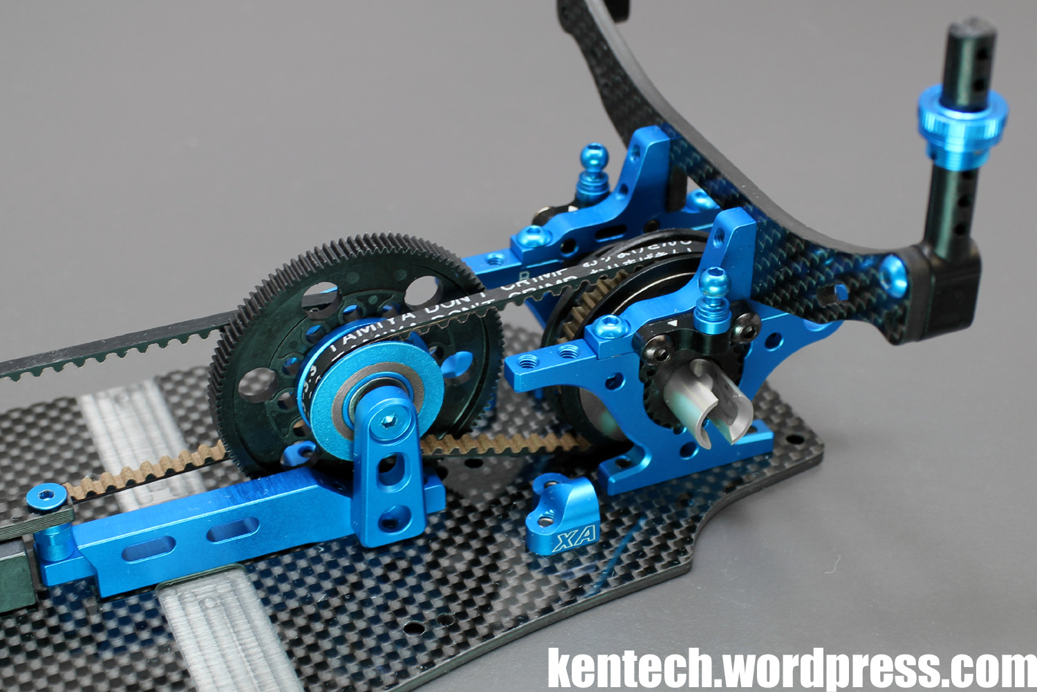
Both the rear diff and front spool are mounted in the low position in the 419XR manual, as opposed to the 419X where the initial position was high.
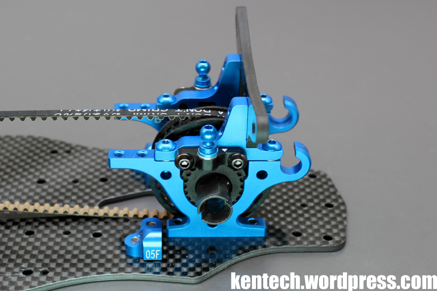
The new bearing supported roll-bar system works well, being easy to work on and setup as well as solid and precise.
As only the inner alu mount is new on the servo mounting, the old parts are attached to the inner part, here with the servo already installed.
I have already shown you the updated upper deck previously in this post, but this is what it looks like in the car.
The fitment is fairly tight around the pulleys, just like on the 419X, so be careful that they spin freely without touching the upper deck.
Also check that the ends of the upper deck are not too tight against the upper bulkheads. There should be a bit of distance between these to avoid tweak issues, so shave the upper deck if needed.
As I mentioned earlier, the V opening at the front of the upper deck is slightly larger on the XR.
The same 10g weights from the X fit the XR chassis as well, so in total you now have one 45g center weight, and two 10g weights.
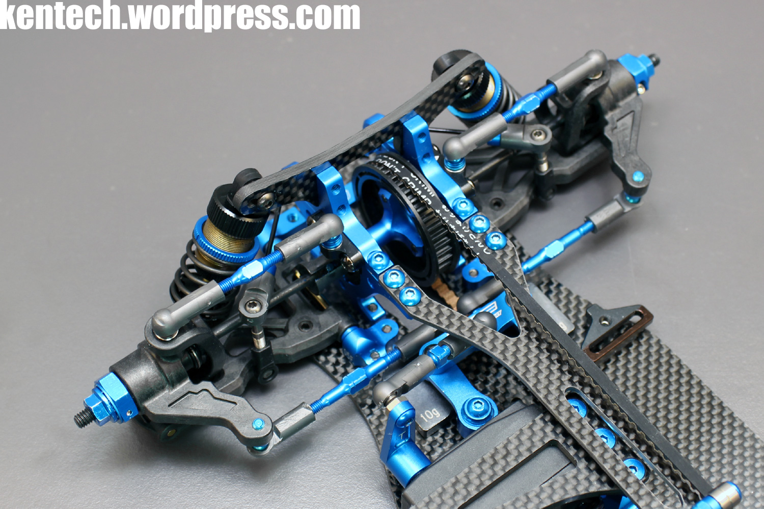
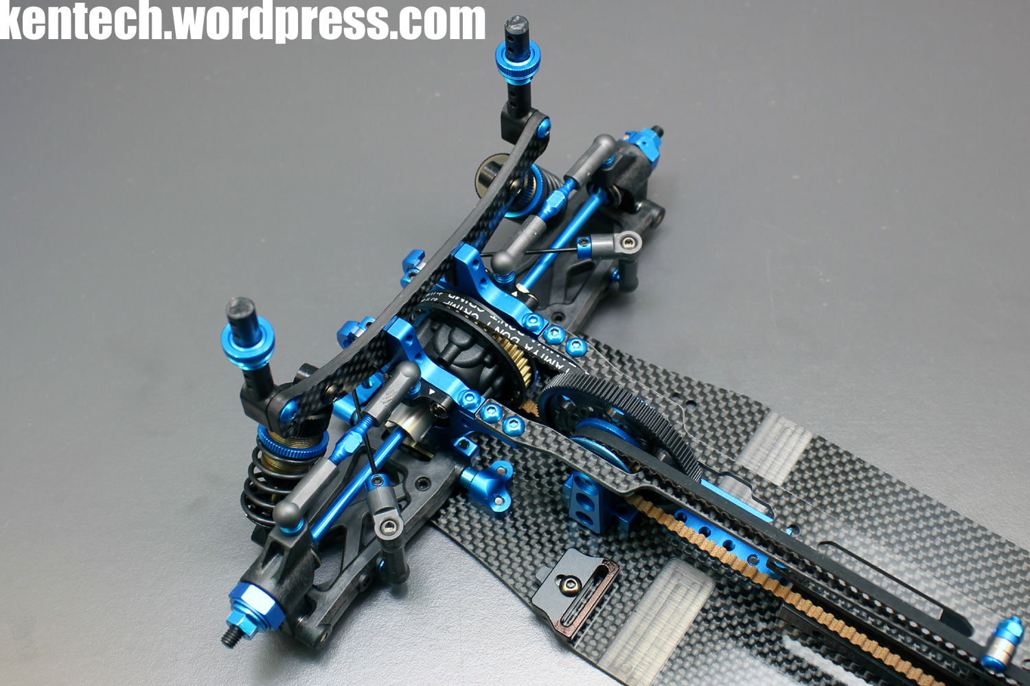
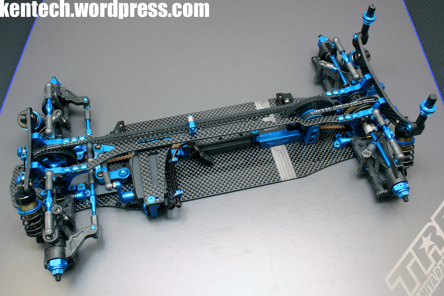
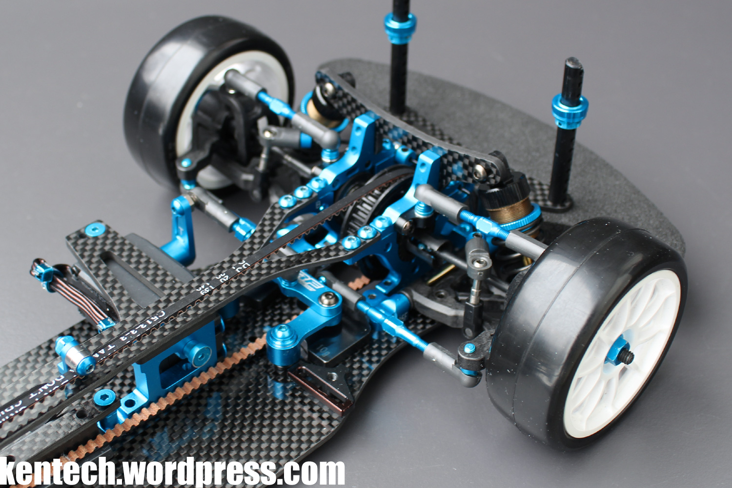
Overview of the almost finished TRF419XR chassis.
With the 0.1mm thicker lower deck and new center stiffener (in its stiffest setting per manual), the 419XR feels fairly stiff.
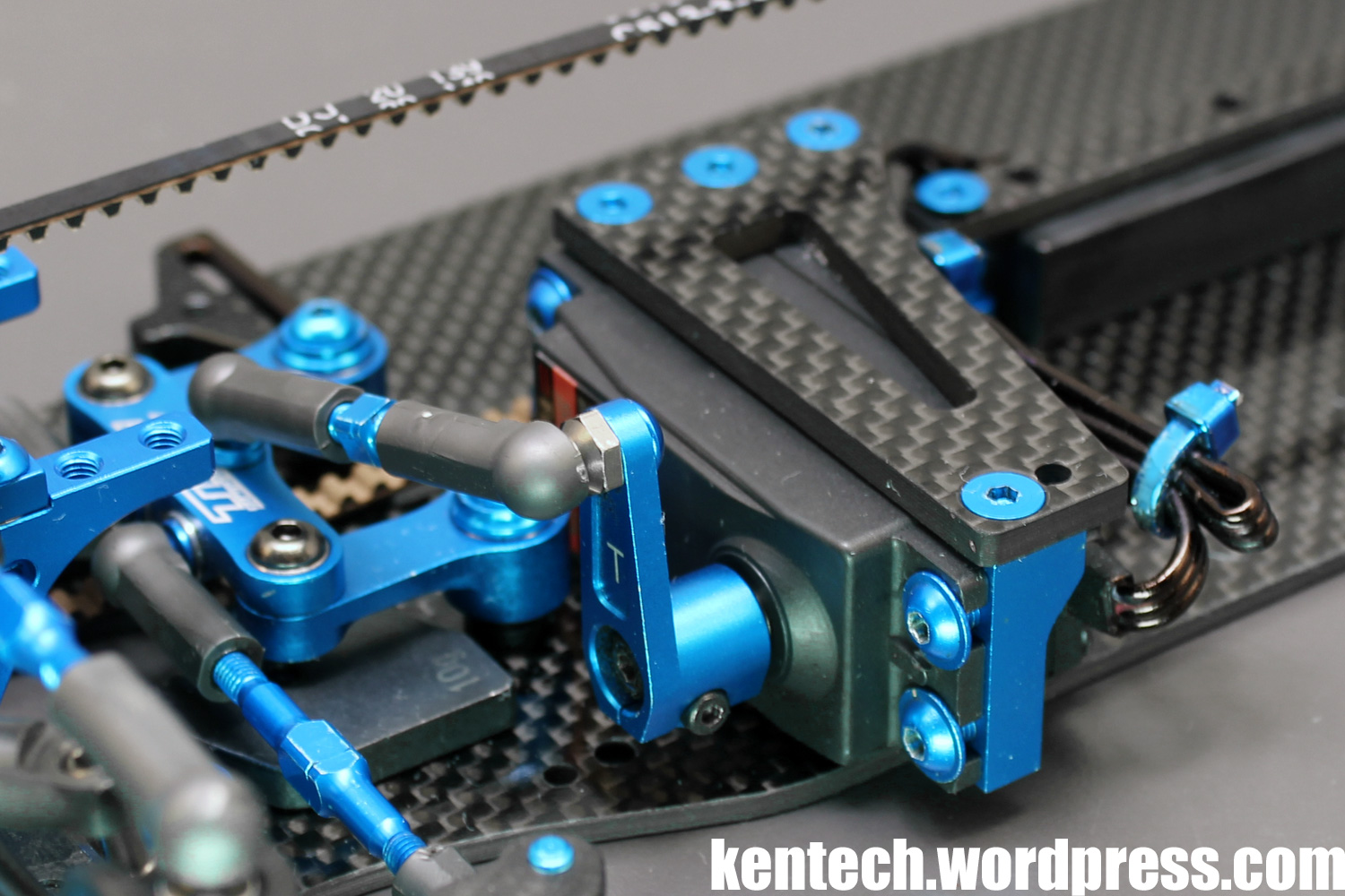
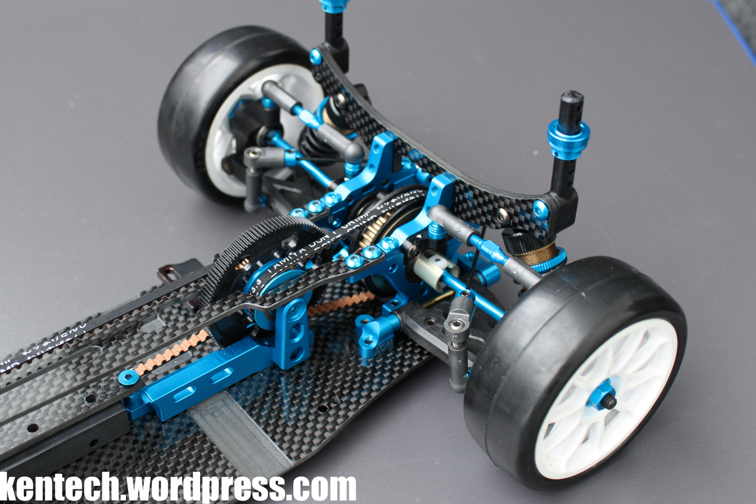
Finally a look at the new cooling fan post included with the TRF419XR conversion set. An elegant and lightweight design with mounting holes for both 30mm and 40mm fans. The post itself fits into a hole at the base of the motor mount, and is secured with a small grub screw from below (through an access hole in the carbon fibre lower deck).
That’s it for the TRF419XR conversion then. Thanks for reading!
Overall I feel this is a good refresh of the TRF419X, which in itself has been of the best TRF cars ever in my opinion. Hopefully the XR will take the platform even further. With a track available to test at, I look forward to properly testing it on track soon.
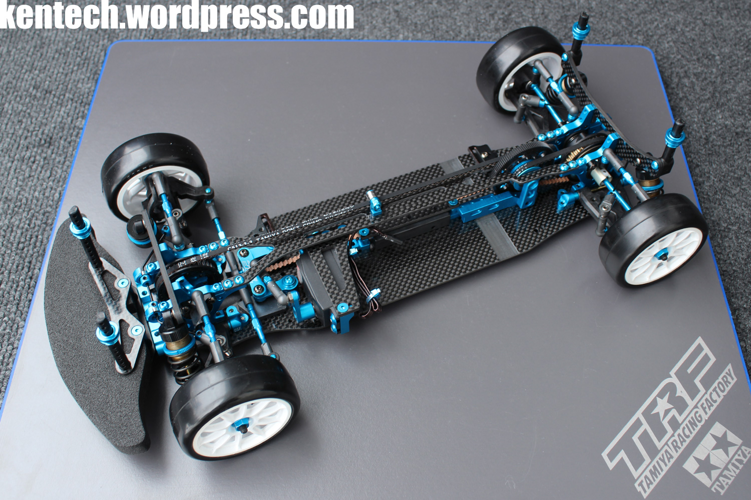
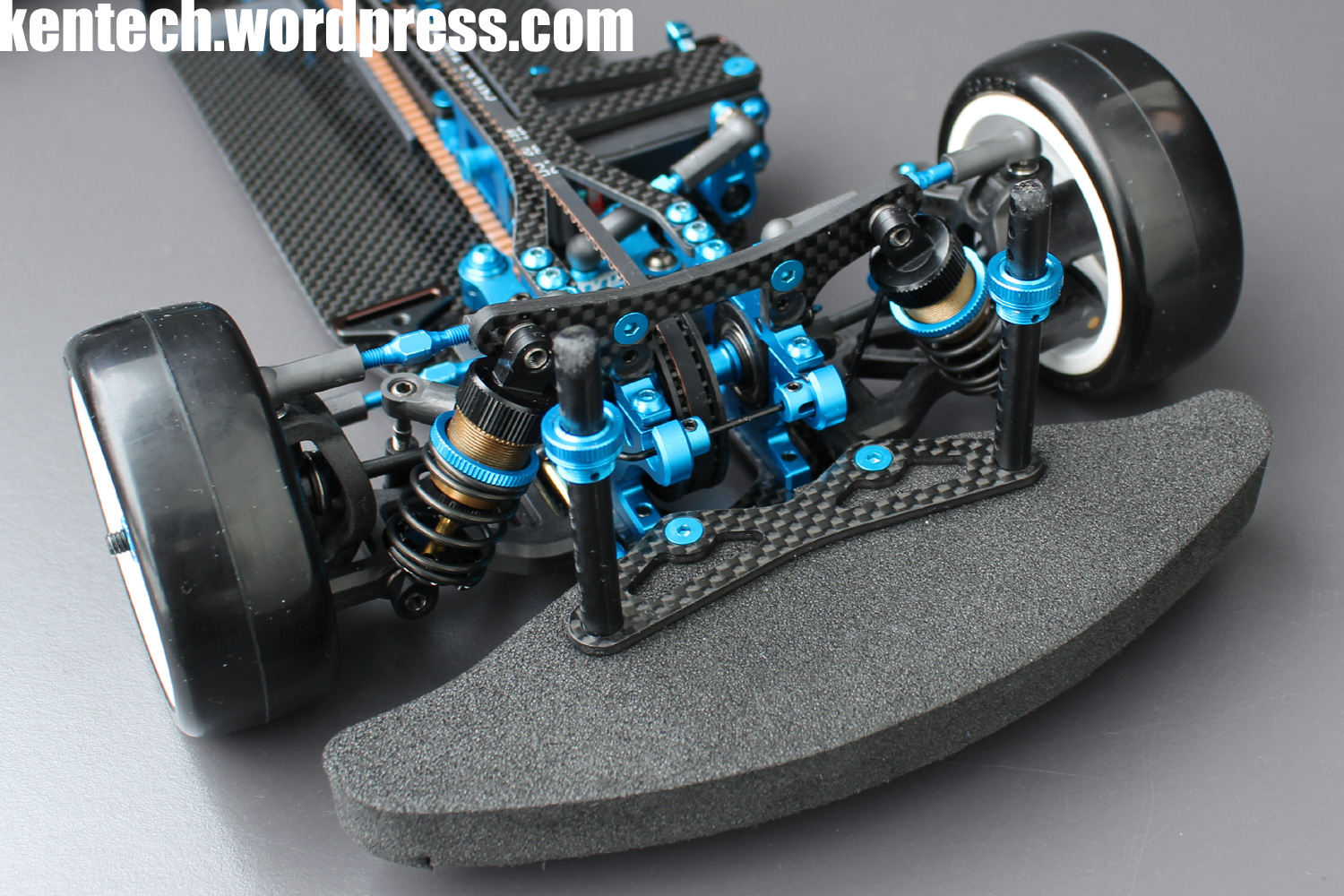
I will leave you with a couple of pictures of the completed TRF419XR chassis on wheels, spoked wheels of course! 🙂

Posted on December 6, 2017, in Uncategorized. Bookmark the permalink. 19 Comments.

Hello Kenneth ~ I am in Hong Kong, can I ask where I can buy this kit ? Thanks~
Sorry, I don’t know anywhere it is available right now (where I got it from has no more stock), but for sure it will be available soon from many shops.
OIC ~~ Thanks for your reply 🙂
Well allways thought that ball bearing supported mount is a stupid invention. Pioneered by morons like xray. Havier, higher CG while there is barely any movement (and less centering). Offroad cars don’t use them and real cars neither. You should do a comparision. Praying BD8, TF7,.. will not do this.
Great review as ever.
I would love to see someone build a jig of some sort that measures the actual difference to flex that some of these adjustments make. I just cannot believe that there would be any measurable difference between the various ways you can attach the rear motor mount.
I’m also intrigued by the return of the centre stiffener. I remember when it appeared on the Yokomo SD SSG many moons ago – and caused major issues with tweak. The current fashion is to have only two mounting points which should make tweak very unlikely unles you are ham-fisted with the build, but I can’t help but feel that this is the 2018 fad that will quietly disappear from the cars again next year.
Thank you!
Totally agree that it’s time for some more scientific methods to measure flex on these cars and to better understand it.
It will be interesting to test the different options available on the XR, also on the motor mount, to see what effect it has.
Definitely way too much of the designs on these cars is about trends. At the same time the cars today in my experience really handle well compared to even some years ago, so there is definite development and progress after all.
I just came home from a first shakedown with the XR, and while I did very little testing, I tried back to back with and without the stiffener, And interstingly one thing I found was that the centre stiffener was very effective in avoiding tweak. Running without it it was much easier to pick up a bit of tweak during the run.
But don’t want to draw any conclusions yet as it was just a shakedown test, getting used to a new track and the new car, checking that there were no problems. A lot of testing to do to get a better idea.
Hey any idea if the new stuff will mount on the old chassis?
Do you mean the 419X chassis? If so, yes it will, but obviously it does not have all the optional holes for the motor mount.
If you mean the original 419, then no.
I have a 419X WS kit, and the XR conversion set – for racing on grey low/medium grip carpet, do you think that the XR chassis + top deck or the WS (alloy) chassis + WS top deck would be the preferred option? Thanks.
As I don’t have the WS alu chassis myself I can’t really say. The car is really good on low/med carpet with the std carbon chassis though. But since I have not tried the alu option I can’t know if that is better or not.
I just got my conversion kit and started right away.
I noticed when I was assembling the center shaft in the spur, that i wasn’t able to push the shaft through the main pulley from my 419X. I missed the smooth fit.
Did you encounter the same problem, because u don’t mention any issues with it?
No issues like that for me.
I have both a conversion kit 419xr and a full 419xr from Japan. On the conversion kit I had the issue of the 5mm OD shaft not being able to fit through the alloy pulley–a quick run through with a drill bit (7/32″) fixed it. On the full 419xr kit it was perfect as is.
@Bart: totally had the same issue and was shocked this was possible in a final release.
Contacted my local dealer and he was surprised too. Couldn’t help me though. Guess I need to drill as Jay did.
@Jay Lestingl: Would you be able to send me the original manual of the full 419XR kit? This would be great! email is patrickrebmann(at)gmx.de
Full XR car kit (42316) manual available here:
Click to access 42316.pdf
Hi Patrick,
I only have the one original full kit XR manual and would prefer to keep it when/if I eventually sell the XR. I don’t believe there are any differences in the manuals (besides one being a full manual and one being an addendum) between the 419xr conversion kit and the full 419xr kit. The only difference between the kits I can remember is the full XR kit includes the blue spring retainers whereas the 419x parts that you reuse in the XR conversion kit uses the black spring retainers. Also, the full kit includes the steel L-shaped battery brackets and a set of tall shock towers that will fit any of the traditional TRF shocks that use 25mm springs.
Pingback: Rebuilding the TRF419XR | BLOG KENTECH
Pingback: Tamiya TRF420X Presentation | BLOG KENTECH
Pingback: TRF Race Team Comeback? | BLOG KENTECH