AXON TC10/3 Detailed Presentation
* UPDATED – Like I promiesed I have now added and updated some info *
Axon is still a relatively young company in the RC business, with the first products launched early 2016, but the people behind it have long experience of working in this field and at a high level. For the first 5 years Axon concentrated on producing general accessories like bearings, springs, spur gears and various chemicals like damper and diff oil, special greases etc. Touring car dampers were quite quickly added to their line-up of products, and throughout this phase Axon built themselves a name with seriously high quality products for the racer.
In 2021 Axon made their first move into the touring car market with the release of the TC10 conversion kit for the Yokomo BD10, and followed it up in 2022 with the updated TC10/2 version. This was also the year that they signed Akio Sobue to move over from Infinity, and be Axon’s lead driver, showing their intentions for the future. They were off to a great start with two cars present at the 2022 IFMAR ISTC Worlds and both finishing in the top ten – Akio on the podium in third and Hayato Ishioka 9th. This was in addition to great results at ETS and winning the JMRCA All Japan TC championships. This run of good results also continued throughout 2023, showing Axon’s potential as one of the top teams in ISTC racing.
Although it had been somewhat of an open secret, finally in early September 2023 Axon announced that they would use a prototype of their first full touring car kit at the 2023 JMRCA championships, which Akio then duly won. The first details of the car was shown early November, with full details released at the end of the month, and a December ’23 release scheduled. The planned release date was at the end of December, but it turned out that they could only deliver cars for the Japanese market on this date, with the rest of the world having to wait until the end of January 2024.
Now it’s now time to get deeper into the build of the TC10/3. However, I will already warn you now that this will be a rather long and detailed article, since this is the first car from a new car maker, and you readers have shown a big interest in this car.
I will begin by saying that Axon has absolutely nothing to do with the fact that I’m building the car and presenting it. In fact, because of them it was even close that I decided to not get the car at all, but in the end I decided I want to see it and build it so I bought the car myself from a normal shop.
I have had a big interest in this car since the start, and the feedback from you the readers have been the same – you want more! Because Axon is Japanese there is sometimes limited information available in English, and for these reasons I have posted extensively on the car since when it was just a prototype. As the release was announced I was in contact with Axon for quite a while, but the way this was conducted and handled by Axon is what almost turned me off from getting the car at all.
In short, I will say that it seems that this side of Axon is not yet up to the high standard of the products that we have seen from them so far. The way the delayed release of the car has been handled with lack of information and communication is further evidence of this.
Now let’s turn our attention to the car itself though!
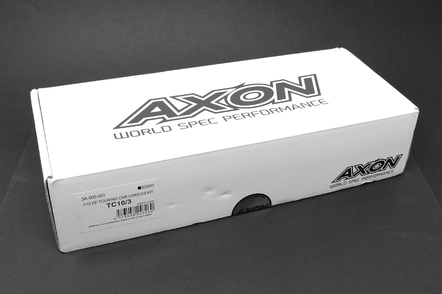
The TC10/3 is not an affordable kit, but neither the most expensive. Checking prices in EU, the lowest I have seen is 689 EUR while 719 EUR seems to be the common price for the car.
It comes in your normal TC size kit box, and I must say I quite like the simple design of it, of course helped by the fact that Axon have a good logo.
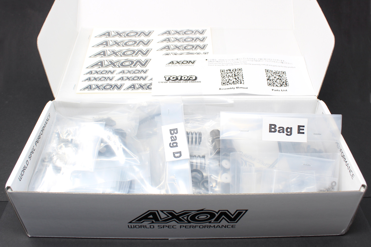
Inside the box you find the parts packaged in bags from A to E. The parts are really nicely packaged with separate small bags inside the main for most everything, but the way it is structured is a bit strange, as if you build the car according to the manual you are constantly jumping between bags. No real issue, and certainly not the first car like this, but in later years this has been quite uncommon.
A set of pre-cut Axon logo decals are included, but no printed manual. Instead you get a QR code that takes you to the PDF manual on Axon’s website.

The manual is 11 pages short, and there is only the minimum amount of info there in a very compact format. It is just about enough to build the car without frustration though, and the illustrations are really quite good.
Overall it could be a bit more generous with information, but even though it’s so minimal, the manual certainly does a better job than various other new car makers. I still think a 700 EUR kit should include a printed manual though.
Another point of difference compared to many other car kits is the way the assembly is organised, as on the TC10/3 you basically start by building all the various components before finally mounting them to the chassis.
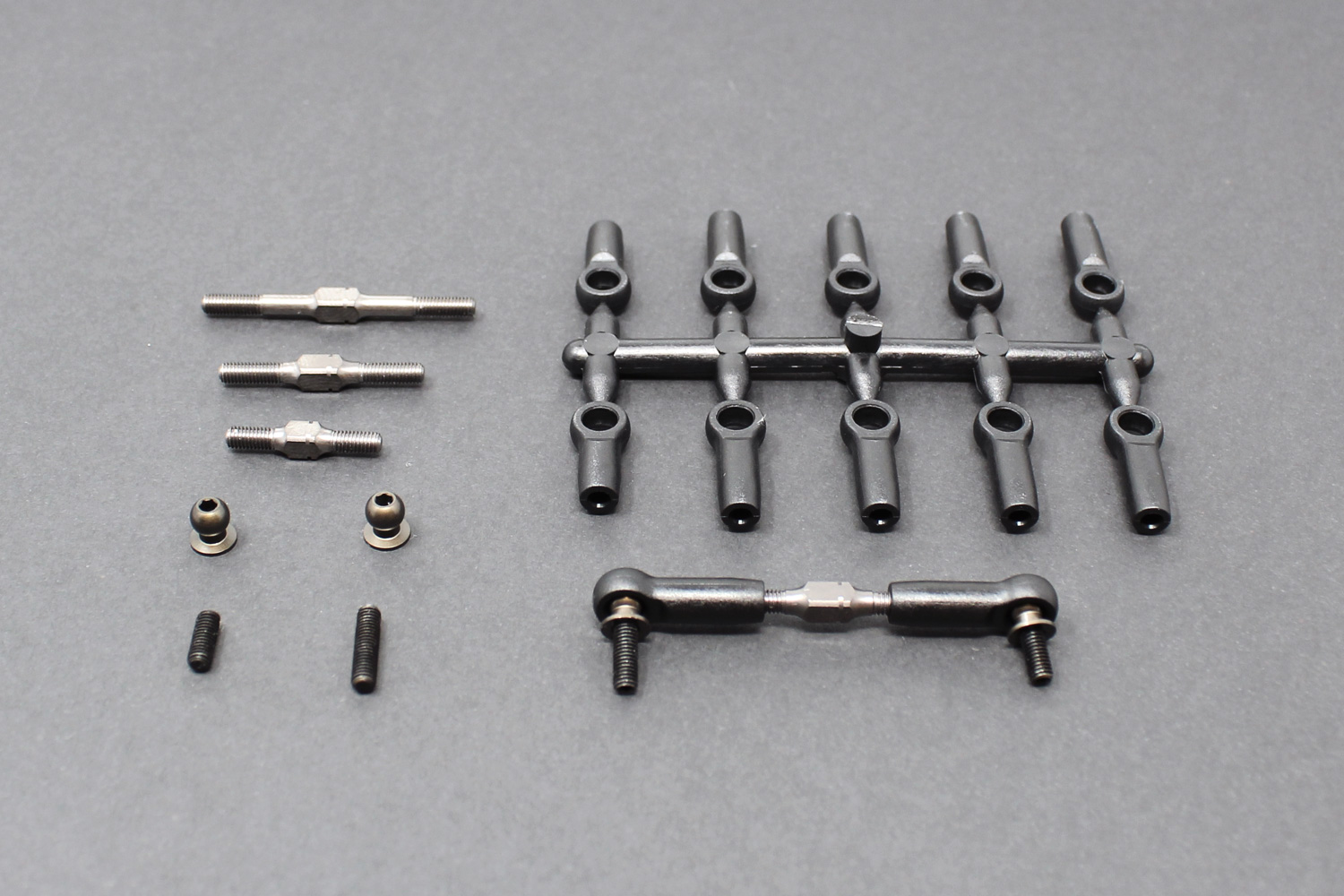
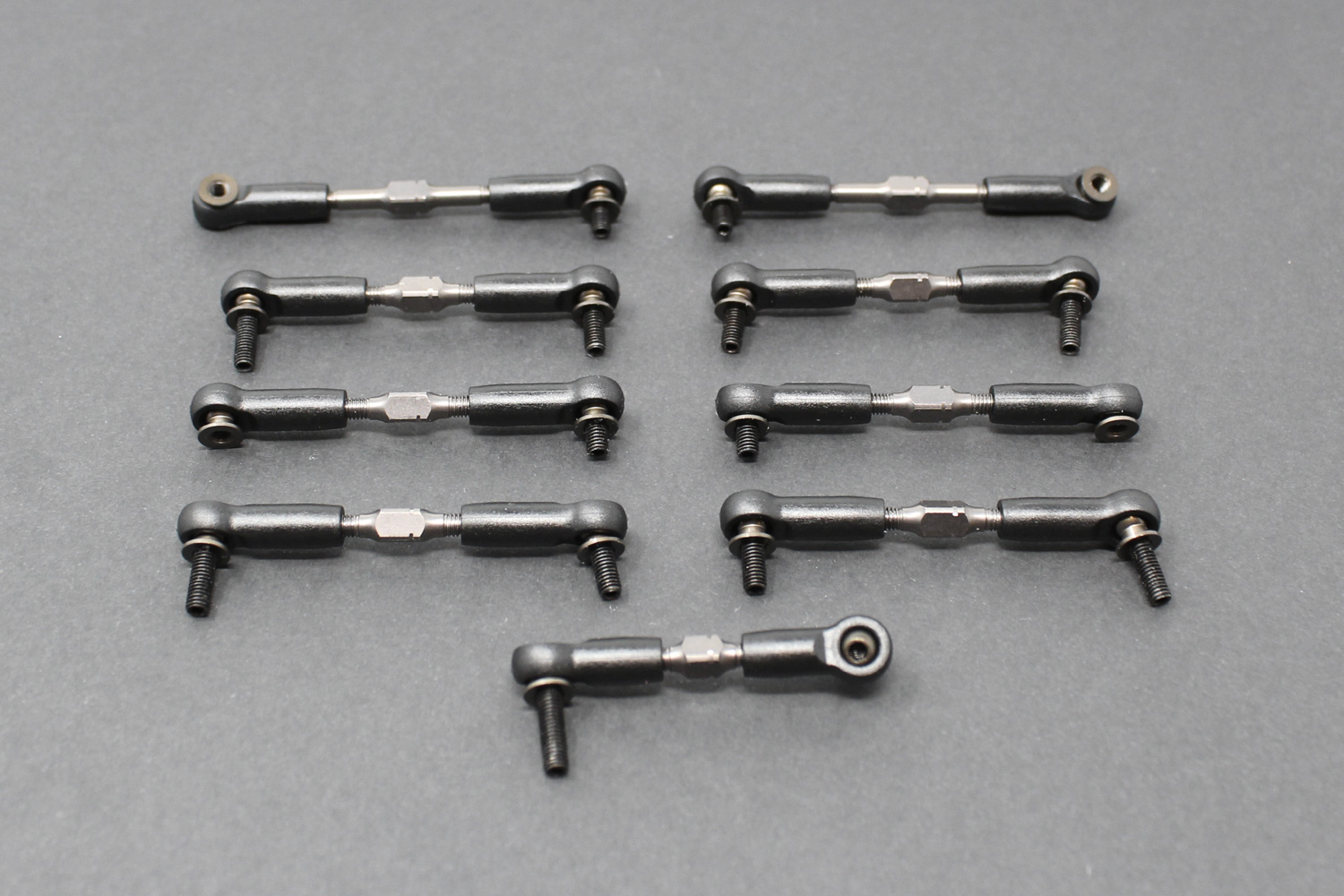
Step one is therefore all the turnbuckles of the car. The turnbuckles and hex balls are aluminium and give an impression of really good quality.
The balls used for the various links are 5mm in diameter, with a 2mm hex. Set screws are inserted into the balls, with various lengths between 8mm and 14mm used.
The precision and fit is excellent, and this is perhaps no surprise as these parts got extra attention from Axon when making the car, as they mention themselves:
“The ball joints around the suspension and steering are key parts that greatly affect the performance of the machine. In order to achieve stress-free operation even under heavy loads, we paid close attention to the materials and clearances of each product.”
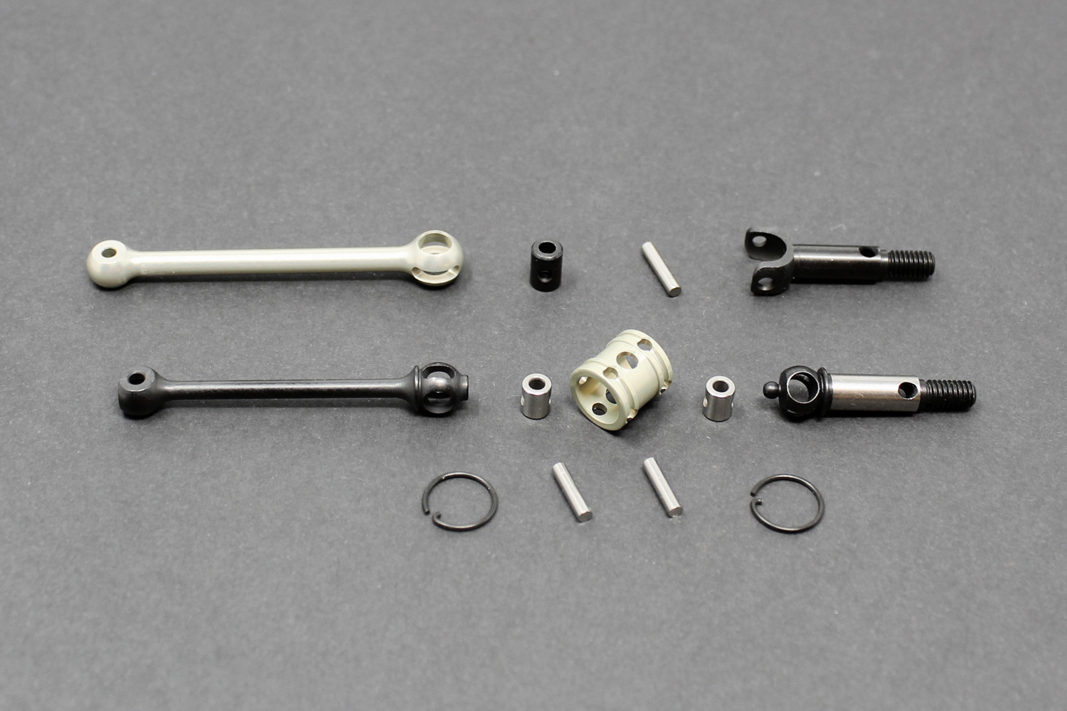
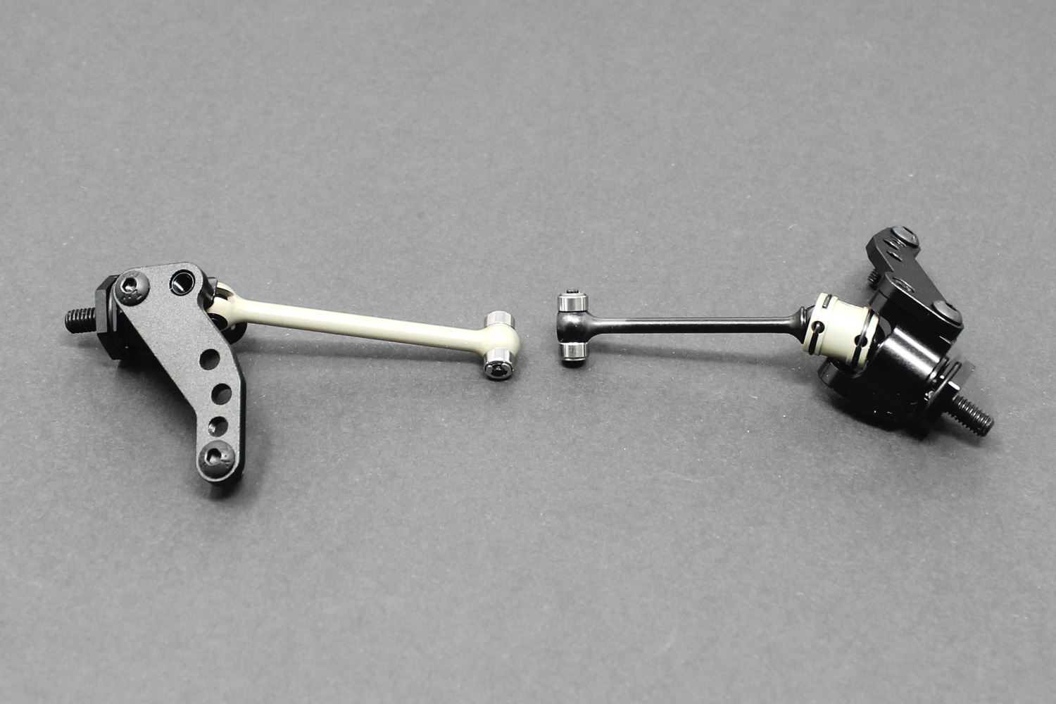
Next up it’s time for the drive shafts and again the look and feel of all the separate parts is one of high quality.
The rear drive shaft has a hard anodised alu shaft with lightened steel axle, while the front DCJ has both a steel shaft and axle, but with a hard anodised alu case. The rear shafts use a set screw to lock the pin while clips are used at the front. All pins used in the drive shafts are 2mm diameter.
There is a bit more play between all the separate parts of the DCJ’s compared to the extremely play-free TRF DCJ’s that I’m most used to. But having built many different cars I guess it’s fair to say that here it’s the TRF DCJ’s the deviate from the norm and not the Axon DCJ’s. Whether a bit more play here is good or bad for performance is not something I would know with any certainty.
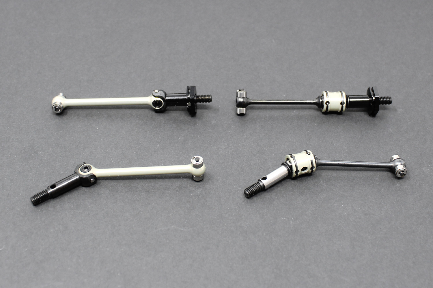
The Axon uses inner bearings on the driveshafts instead of blades or other plastic parts used on some cars. These bearings are 2x5mm and the e-clips are M1.5, and much easier to work with compared to the smaller clips found on some cars.
In place of normal separate wheel hexes the TC10/3 use alu hex axles that slide onto the wheel axle, and are secured with a pin and o-ring. This makes for a precise fit inside the 6x10mm wheel bearings.
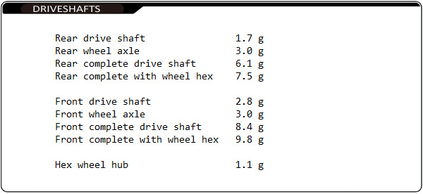
Here you see some drive shaft data.
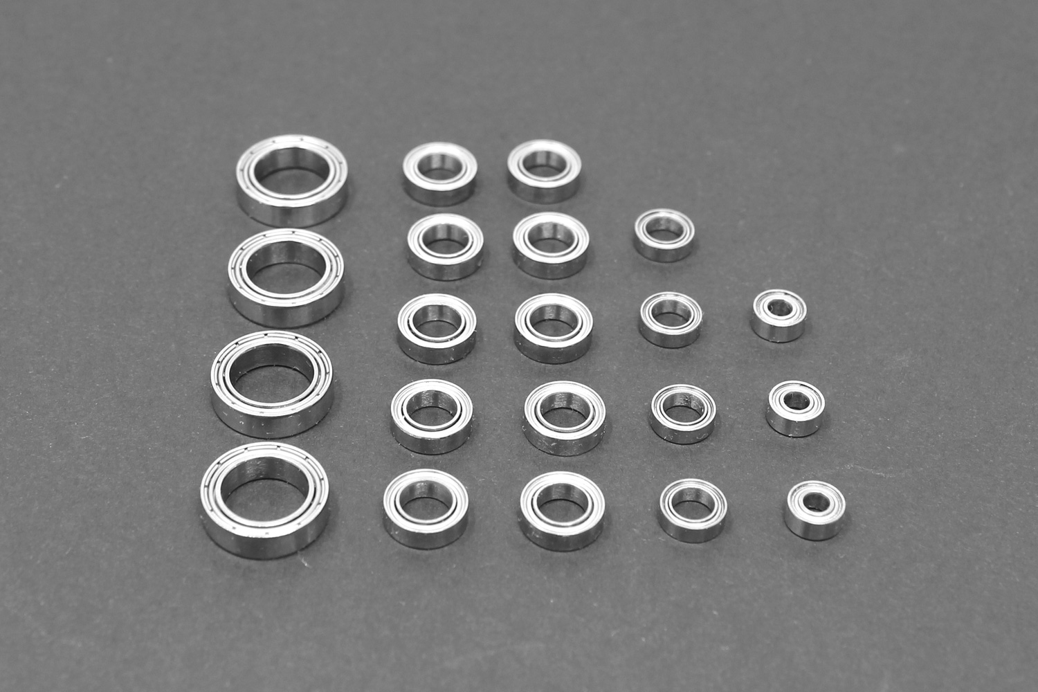
Axon “Sports” metal shielded ball bearings are included.
10x15mm for the diff/spool, 6x10mm for wheel bearings and spur axle, 5x8mm for the steering, and 3x7mm for the belt tension bearings that go in the motor mount (+ the 2x5mm drive shaft bearings).
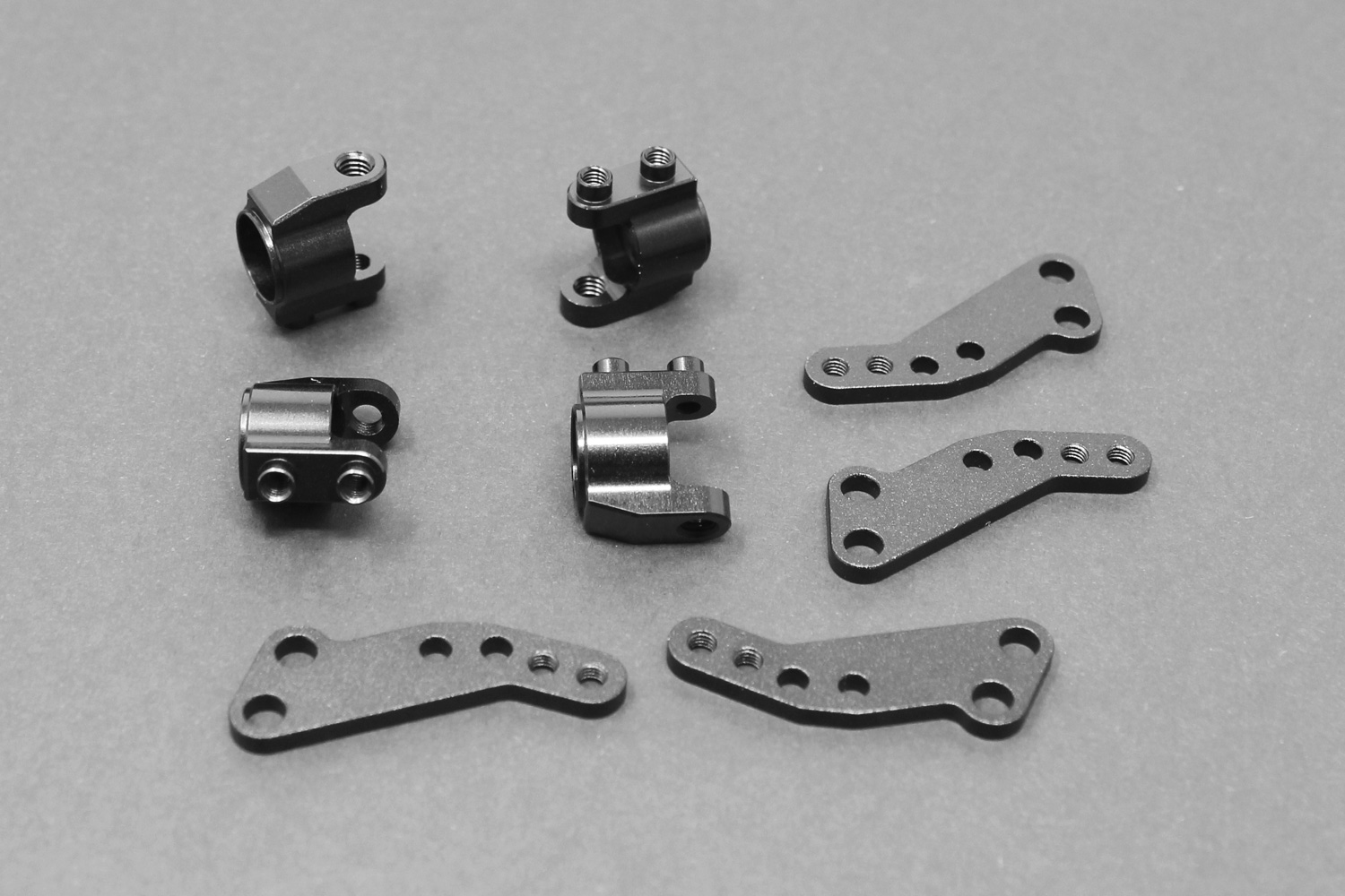
The uprights or knuckles are the same on all four corners and just like the upright arms, which are also all the same, these are made from aluminium and black anodised.
You will notice that the surface finish is different on these parts. Most black anodised parts on the TC10/3 have a dull or slight crackle finish not really seen on other cars. I suppose these parts are machined from 7075 (or similar) alu, while the smooth finish parts are of a lower grade alu.
Again the fit of these parts is really good and the whole upright assembly go together without issues. I would say that the precision in these parts is above almost any other car.
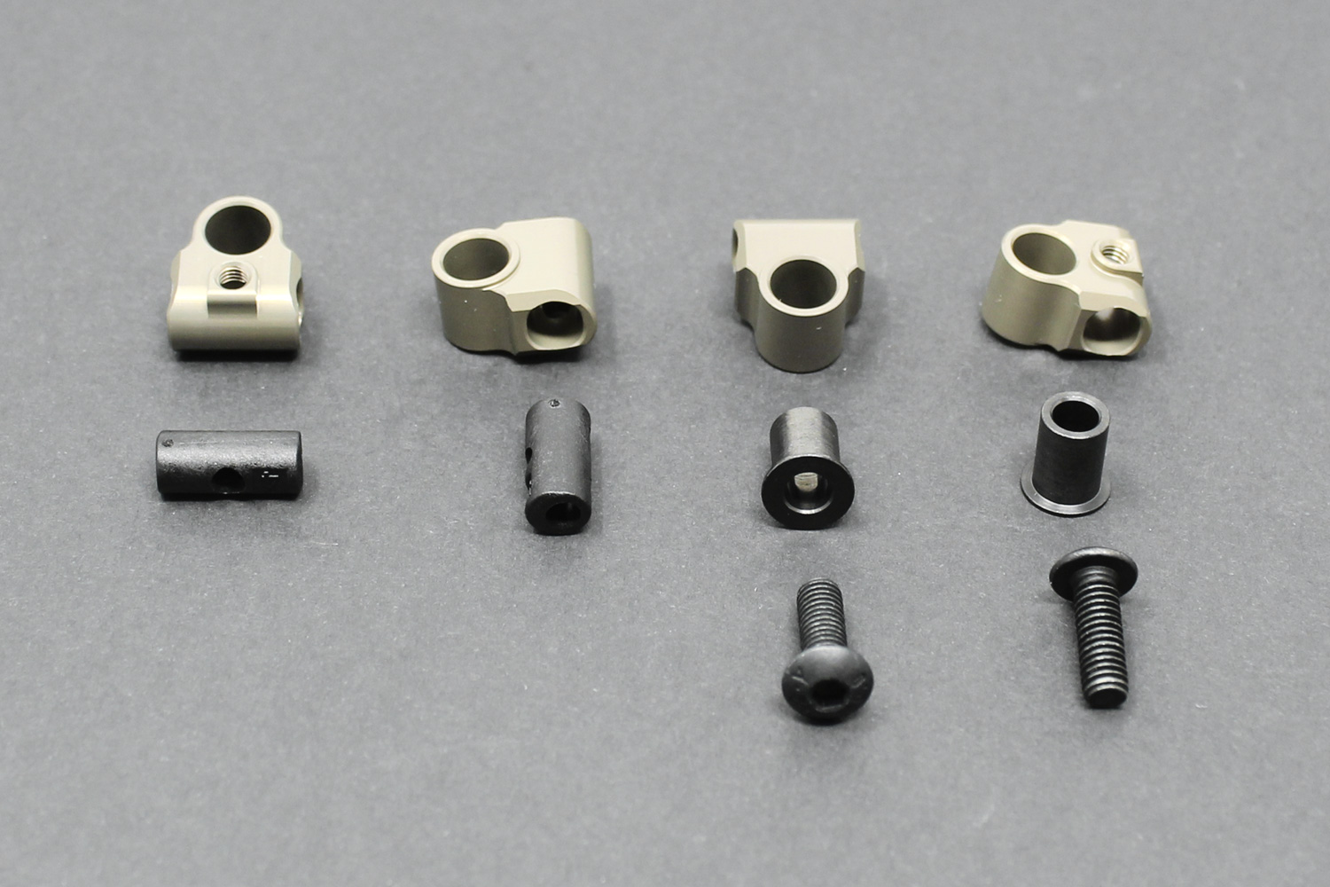
Perhaps the most unique feature of the TC10/3 is in how its suspension is configured. Although not the only car to use an inner pivot ball, outer pin style suspension (e.g. Yokomo do this on the BD11 & BD12), Axon have gone about this setup in a slightly different way.
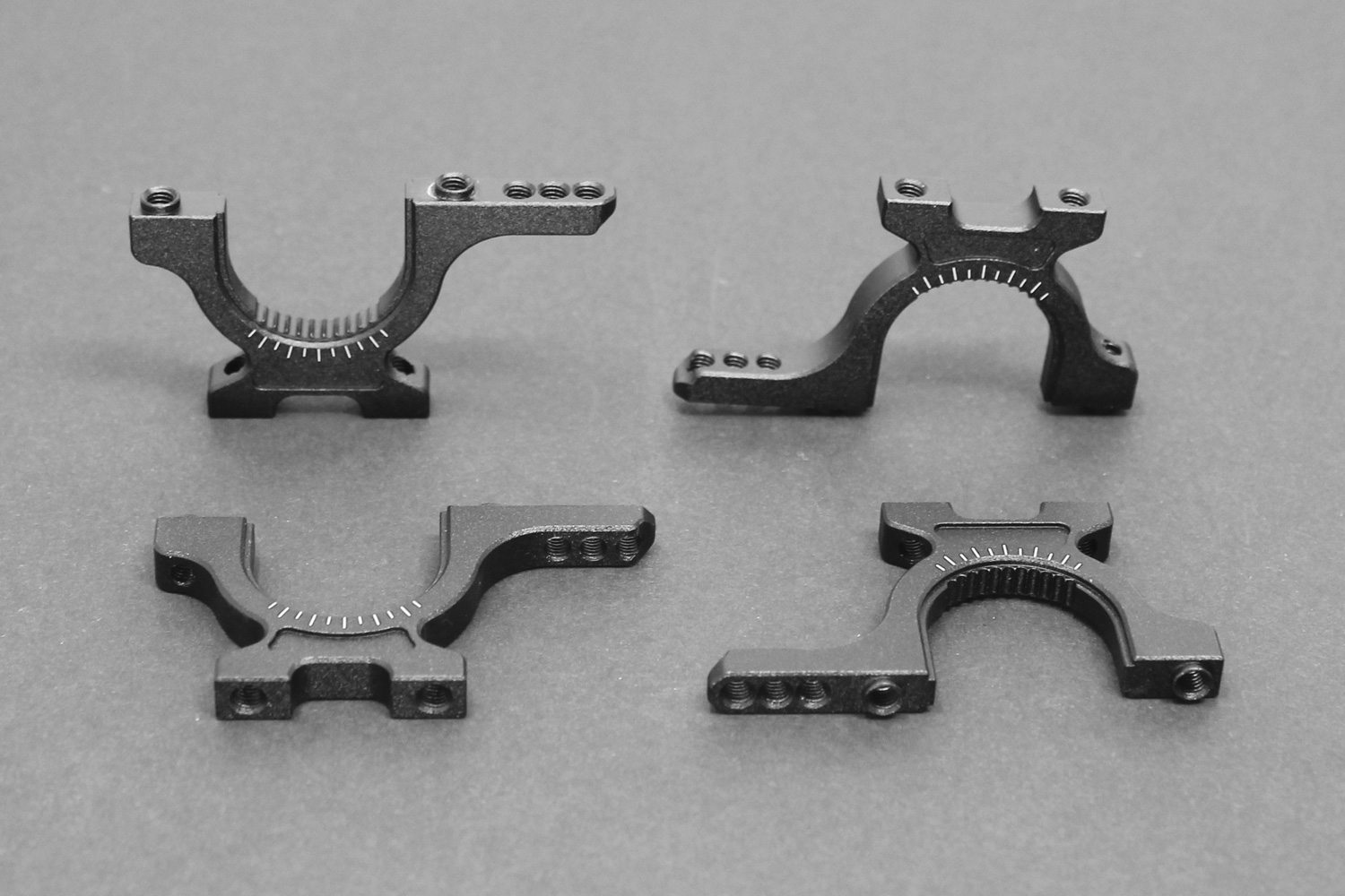
Instead of traditional C-hubs that wrap around the steering block, the Axon uses a small lower alu caster block to support the steering block. Again, this is not the first time a manufacturer has used this kind of idea, but the setup Axon use on the TC10/3 it is rather unique.
The caster block has a different anodising and holds a composite insert, which the hinge pin then goes through. These inserts are exchangable and 5 different inserts are included, letting you change the caster setting between 2, 2.5, 3, 3.5 and 4 degrees. The initial setting is 4 degrees front caster, and -2 rear. The hinge pin is secured with a set screw that goes through the caster block and insert to hold everything in place.
A special large diameter and tall kingpin bushing is used to give enough support to the steering block. Special shims are included and can be used to adjust axle height. An M4x12 screw is then used to secure caster block and steering block. As this is steel it’s quite heavy.

Here you see the upright assemblies for all corners, with high quality parts throughout.
The caster inserts fit precisely inside alu blocks and the whole assembly gives a solid and good impression.
Here is the data on the upright and caster blocks in the order of the photos above.
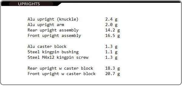
A 38T spool / diff pulley size has been chosen, and this is what the majority of manufacturers use today. Together with the 20T middle pulley it gives a drivetrain ratio of 1.9.
The spool pulley unit itself is all plastic, with steel drive cups, outdrives, or whatever you want to call them. These are held to the spool housing with M3x10mm screws. First you slide the included 5mm alu spacers onto the screws, and these then fit inside the outdrive for a solid spool assembly.
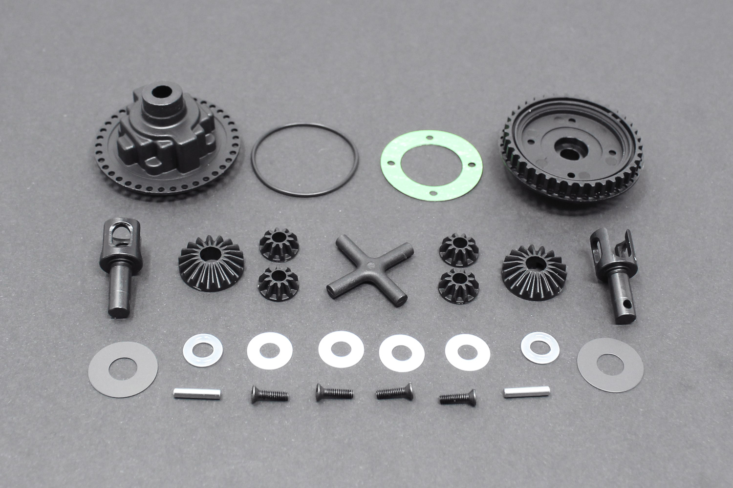
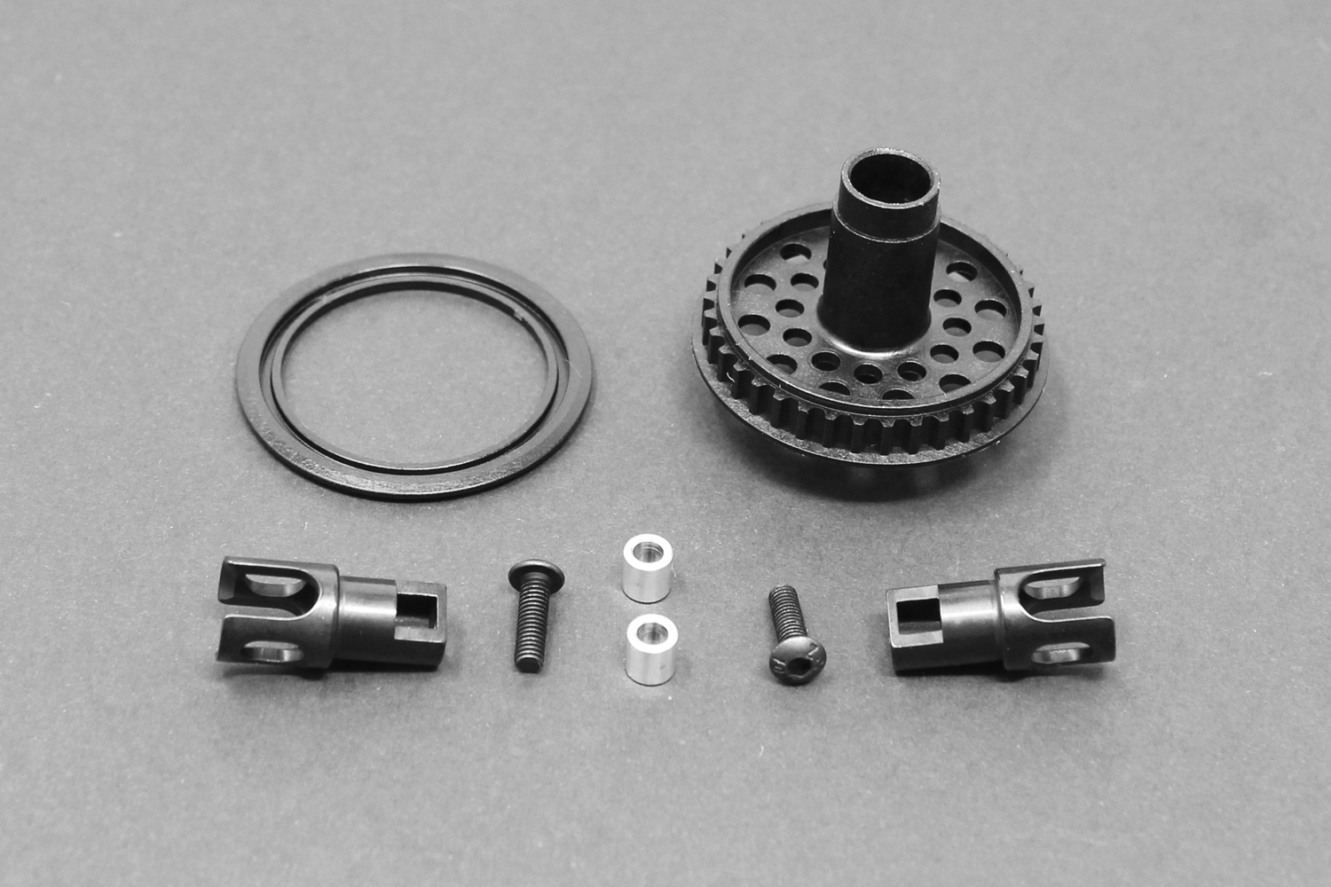
The rear gear diff is again very much a standard basic design that looks very similar to many other TC gear diffs, but Axon’s version cone with small and perhaps important detail differences.
I have not built a Yokomo BD10/11/12 diff, so I can’t say how similar (or the same?) the case and gears are.
Also the gear diff gets steel outdrives and Axon’s excellent gear diff o-rings. The shims are different in material (teflon) to what we see in most diffs and have a larger inner diameter, with the manual mentioning that “the hole size is bigger to improve lubrication inside the differential”. The gears are 10T and 18T in size.
The gear diff is easy to assemble and really smooth straight away.
No diff oil is included, but 6000cst is recommended as a starting point.
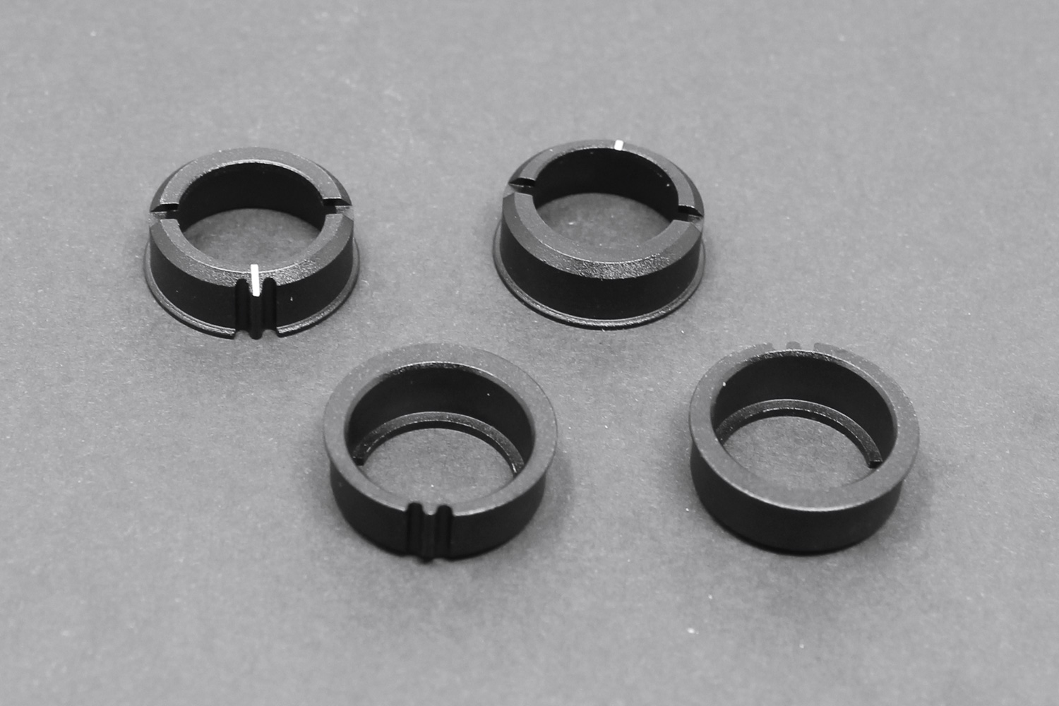
Both the front spool and rear diff bearings go inside these aluminium high precision bearing holders.
Good to see the white mark on them which makes life easier when adjusting belt tension. The bearings fit perfectly and the holders also later have the same fit in the bulkheads, so it’s really good to see these included.
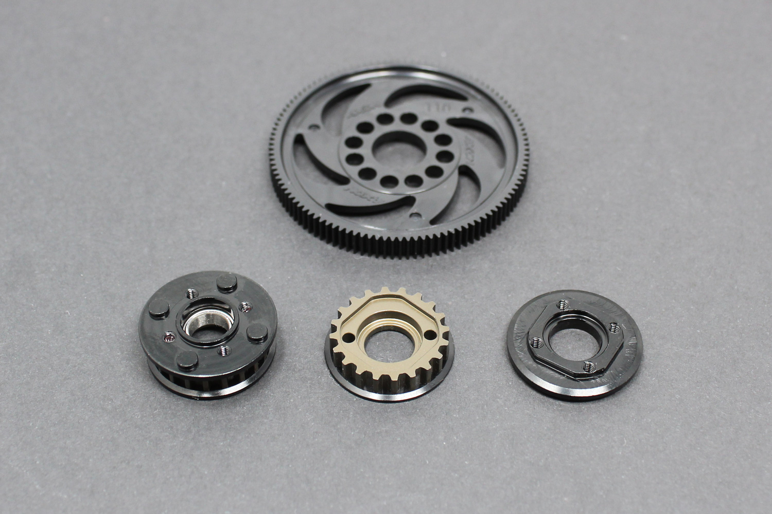
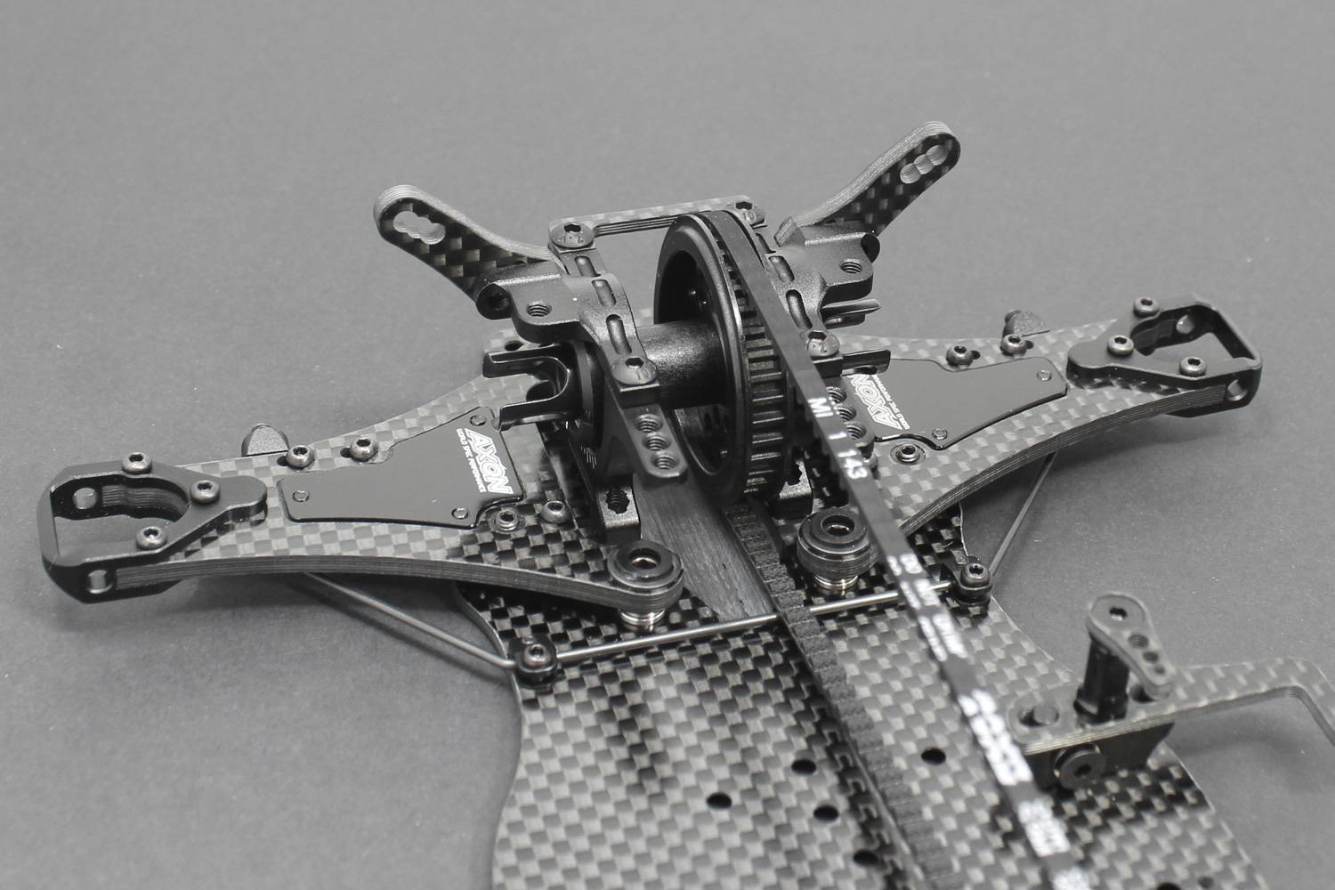
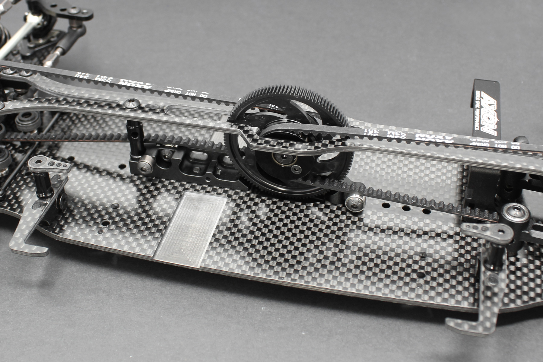
Not many cars place the spur gear on the centerline of the car anymore, with the belts and pulleys either side, but Axon still use this setup.
This drive assembly is well made on the TC10/3 though, with two identical two-piece pulleys holding one 6x10mm bearing each, with an alu cap then screwed on with two small 2x6mm screws. This means no chance of bearings falling out. Finally each pulley assmbly with bearing inside is then pressed into the spur gear.
The design of this also allows fairly easy spur gear changes, as you do not need to remove the upper deck etc. Just remove the axle holding it, and then pop out the pulleys and then the spur.
The included spur gear is of course Axon’s own TCS V2 version, in 64P and 110T size.
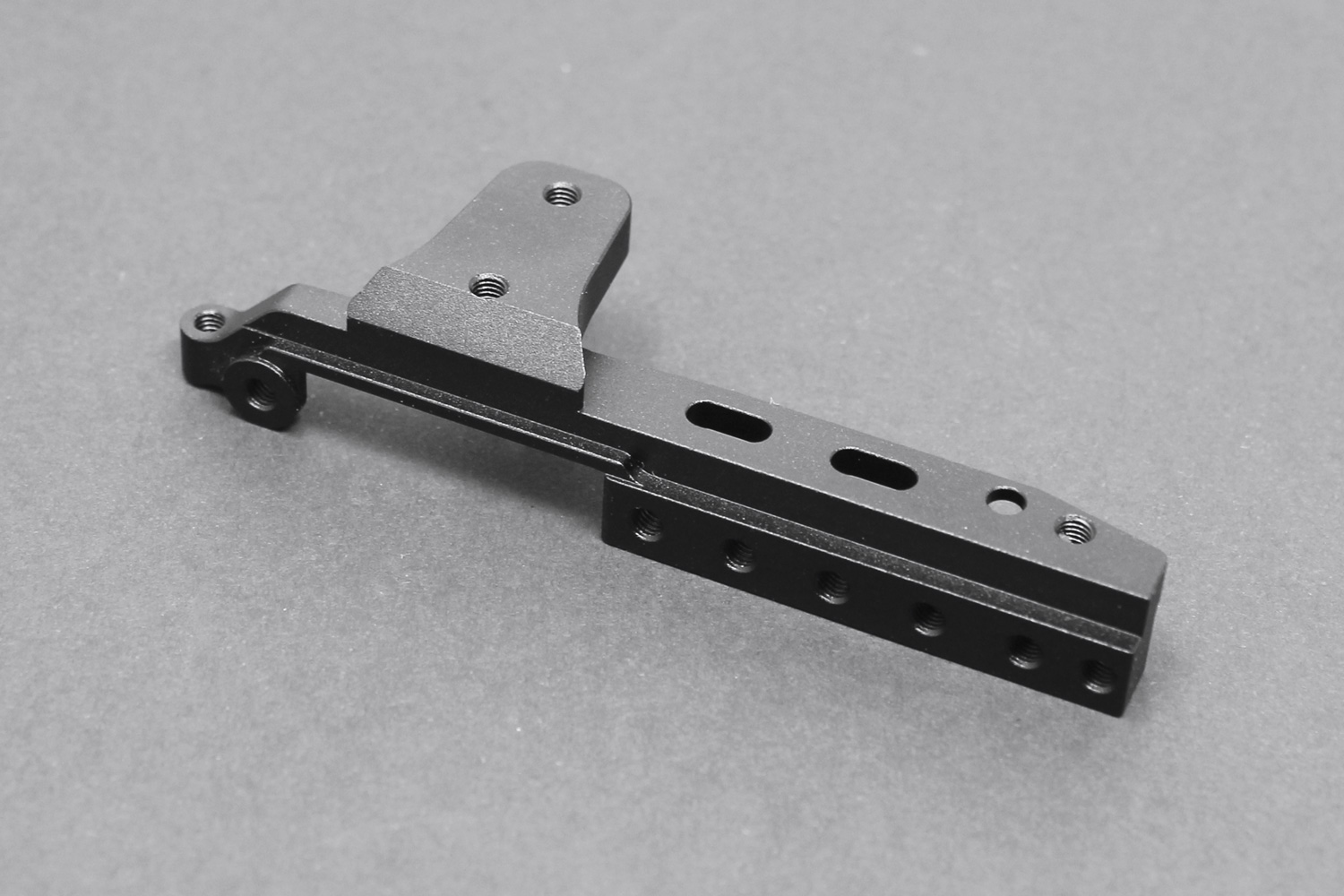
The motor mount is quite simple and low on the TC10/3, but with many flex options for fastening it to the lower deck.
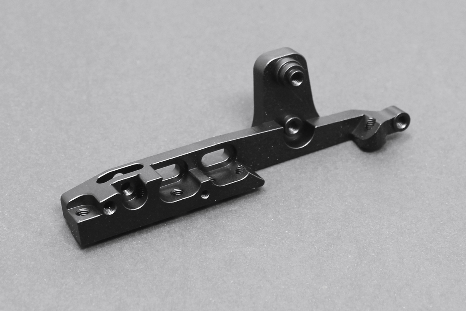
Another view of the motor mount, where you see more detail.
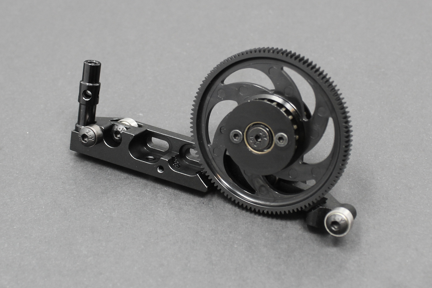
Spur gear assembly fitted, with a special alu shaft and 3x16mm screw used to secure it to the motor mount.
Also added to the motor mount are the three 3x7mm bearings that act as belt tensioners or belt guides. One at the rear, one at the front and one in the middle under the center pulley. I especially like how the rear bearing is integrated into the motor mount design.
A separate “roll post” is used at the rear, to which the upper deck then can be secured later. Since it has a hole through it, it’s easy to tighten to the motor mount.
Drivetrain part weights above.
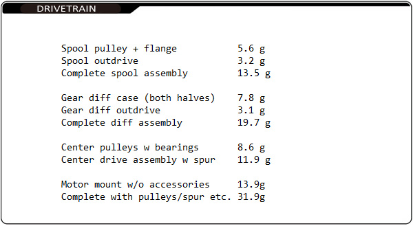
Now it’s time to build the suspension arms for the TC10/3, and even though they are different from any other, they still use a similar multi-piece carbon/alu/plastic design which is common today.
While not the only explanation, one definite reason TC suspension arms have moved in this direction is how easy it is to change the design, compared to making a moulded arm in the traditional way. To get return on investment spent on a mould you need to sell enough of the product, and if you then need to do changes it starts all over again. This is one reason why today you mostly see moulded arms from manufacturers that also make a lot of other moulded parts. For low-volume manufacturers it’s much more flexible to go the multi-piece carbon/alu route. What is better for performance is another question.
The TC10/3 lower arms are based on 3.0mm carbon fibre arms with quite an attractive shape. Front and rear are different, but left and right arms are the same. The only difference front to rear is the holes for the alu damper holders, where these are further inboard on the front arms. Three different positions for the damper holders are offered front and rear.
Plastic parts used for the arms are droop screw holders and ball bushings which are secured with large c-clips. The alu hex balls are listed as 6mm in the parts list but are actually 5.8mm when measured, and these use a 3mm hex.
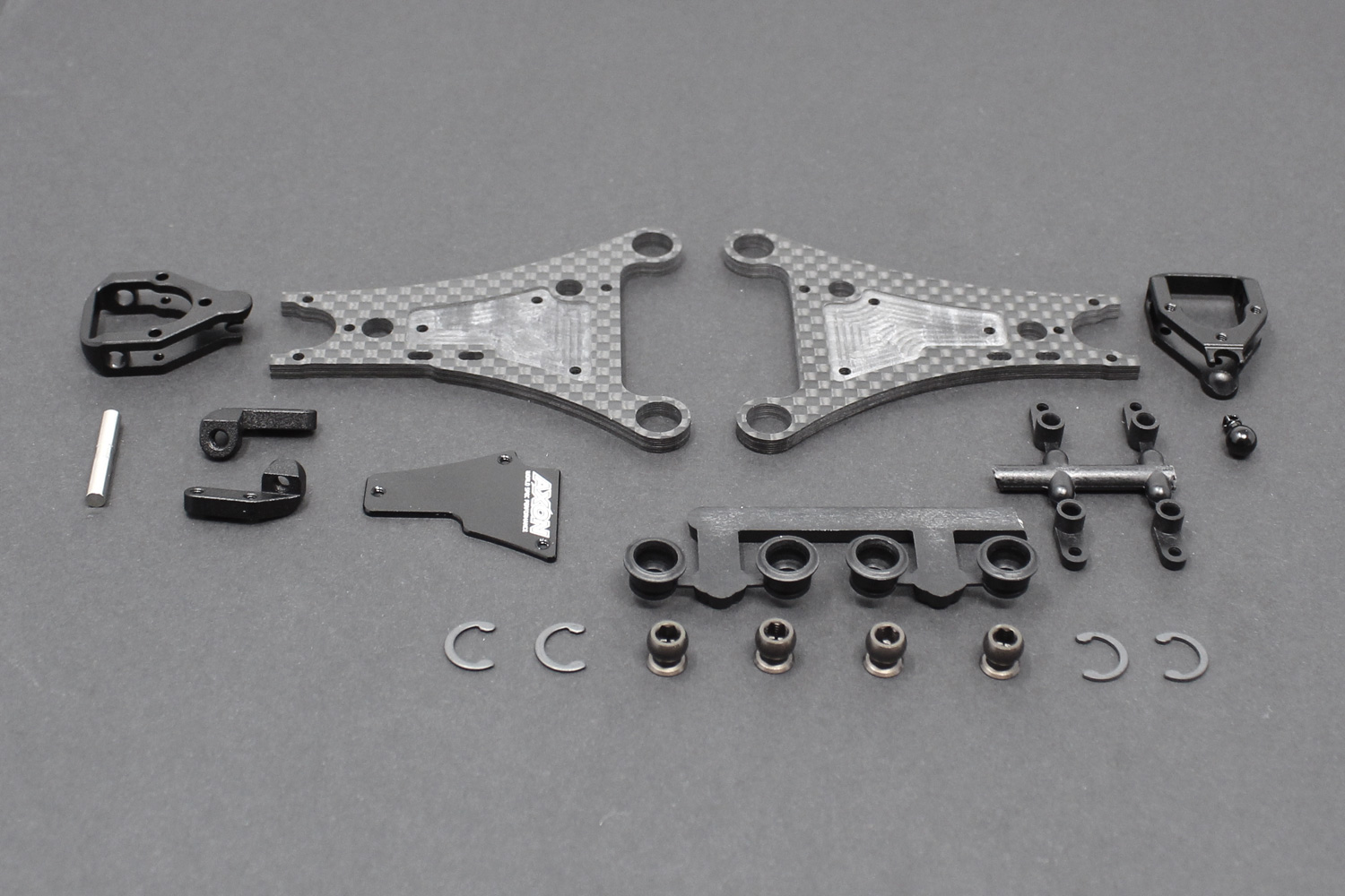
An alu arm plate that is black anodised and with a beautiful Axon logo go into the recess machined in each arm. I have to say that I’m not actually 100% sure of the purpose of this alu plate, but it certainly looks good 🙂
At the outer end is a complex but very slim and light alu part that is secured to the arm and which will then hold the outer hinge pin. These are the same on all four corners. This part also acts as a holder for the large diameter alu roll bar ball, which goes underneath the arm.
Above you see what the completed lower suspension arms look like from the top and bottom. Arm length (pivot to pivot) is 63mm by my measurements.
All the accessories are secured to the carbon arms with M2 hardware.
While all this goes together well with good fit and finish, there is one exception, and this really is the first (and only as it turns out) question mark when it comes to precision. While the alu hex balls fit nicely in the ball bushings, these bushings have a bit of movement within the arm itself, and it varies a bit between each arm, or even hole. It could of course be that Axon prefer to have a bit too much room here instead of risking the pivot ever getting sticky, but it is not really good that the bushings move inside the arms. It is not a huge amount in any way, so don’t let this discourage you. It’s just a question mark.
Having disassembled these parts again to check the parts, it seems that the tolerances overall in these parts are not quite right, as there are small variations in the arm holes and bushes, and this is where the play comes from. By adding a suitable thin and flexible material between these when you build them, this play can be removed.
Another thought about the arms is that there is very little carbon material around these inner pivot holes, and I can imagine arms breaking at this point.

Suspension arm item weights above.

After the lower arms, we move onto the upper bulkheads. These are again the same front and rear.
The damper towers are mounted to the upper bulkheads and are super minimal and split in design. As you can see the bulkheads feature two lugs and the towers are secured with two screws for a super secure and prcise mounting of the towers. This obviously becomes very important when mounted to the upper bulkheads like this.
In addition the lower bulkheads have bosses around the screw holes with matching recesses in the upper bulkheads, to further make this design stable.
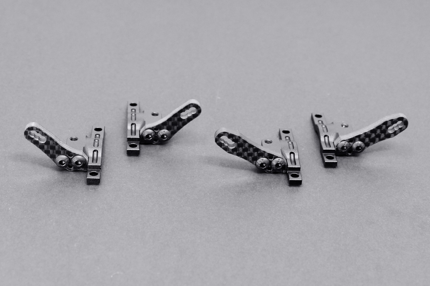
The rear towers are slightly wider than at the front to match the damper positioning on the arms, while there are three different damper mounting options at both ends.
Only one upper arm position is provided, and this will give upper arm lenths of approx. 48mm (centre-to-centre).

This is the rear body mount plate and horisontal 6mm body posts. The carbon used here is 3.0mm thick.
Unfortunately no vertical posts are included, but you can of course get an extra set of front body posts for this purpose, and that’s what I think I will do.
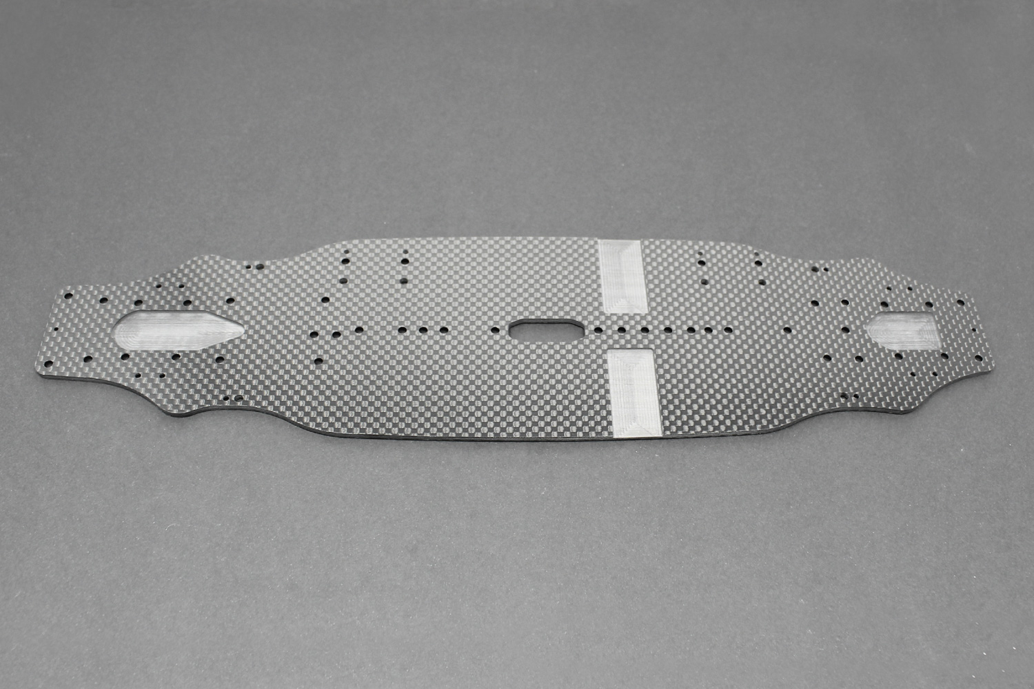
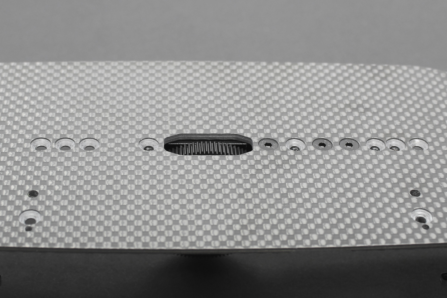
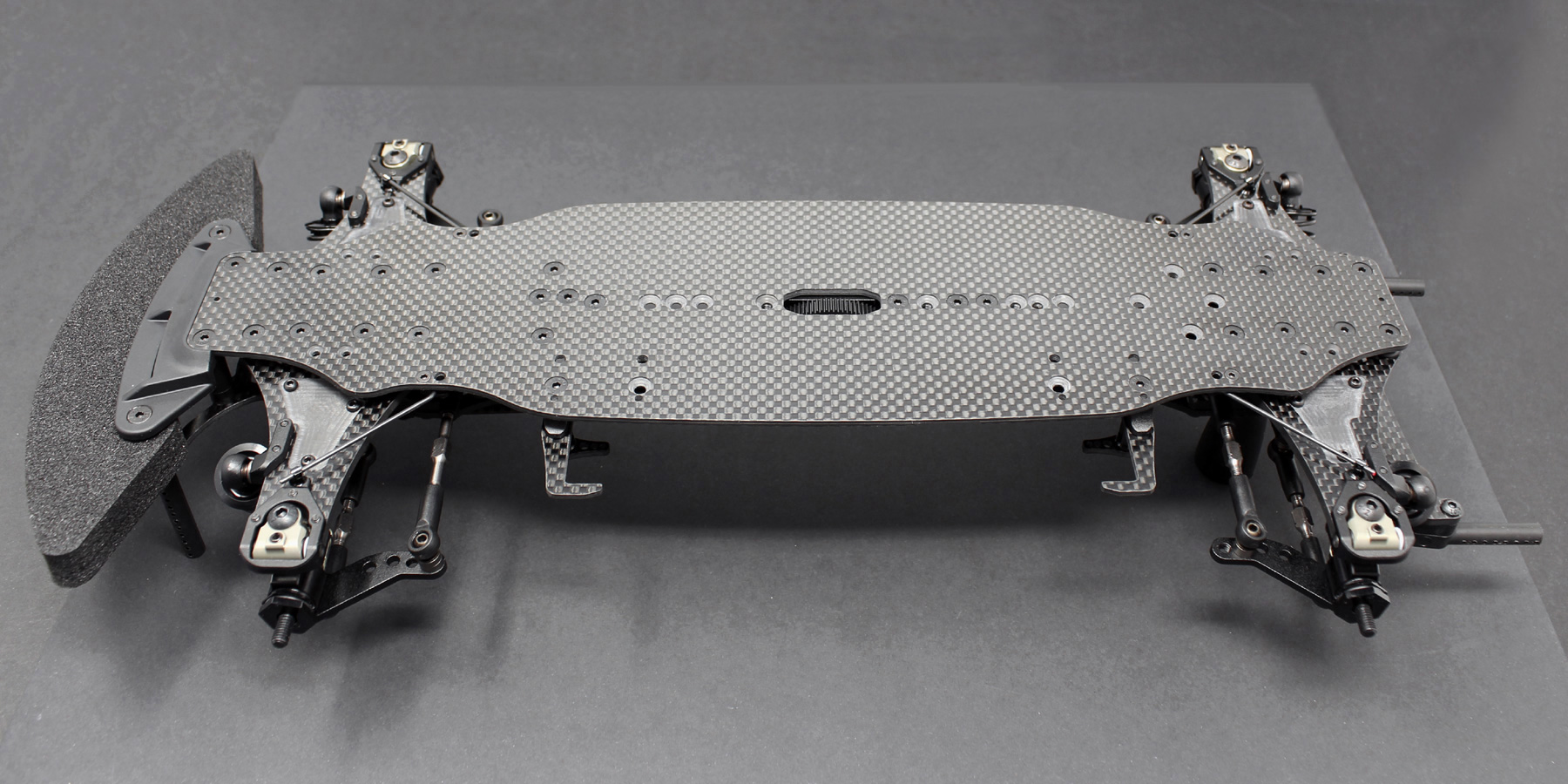
Finally we get to the stage where we see the lower deck of the TC10/3.
The chassis is 2.25mm thick carbon, with pockets (not holes) under the front and rear axle as well as under the motor, and similarly on the opposite side. The motor pocket is 1mm deep.
Lower deck width is a fairly standard 85mm, while it has a slightly rounded shape to try to minimise chassis scrub.
Following the assembly manual, the next build step is the battery mounts, which consists of an alu base, a carbon hook, alu posts and a very small carbon upper holder.
There are battery mount holes in the chassis suitable for shorty batteries as well.
The battery mounts are adjustable in all directions. The carbon hooks slide on the alu base to adjust width, while battery length can be accomodated with screws and spacers. Height is again adjusted with spacers under the upper holders.
In the image above you also see the super small roll bar holders. These are mounted to the chassis with tiny 2x5mm screws, while even smaller 2x3mm screws are used from the top to secure the bar to the holders.

Here the rear arms and roll bar is installed. Both front and rear roll bars are the same, and two 1.3mm bars are supplied with the car. Optionally 1.2mm bars are available.
The way the roll bar is mounted is different to most other cars, and there are no bearings used here. Of course there is a bit more sideways play than if this was the case, but the operation seems decent and tweak-free so far. Only track time will give more info on how well this works.
Special 1mm spacers are included and installed under the suspension pivot balls when you build it to the default setup. By removing these or adding more you can adjust roll centre.
Here you see how the roll bars mount to the arm via the large diameter roll bar ball mentioned earlier. This has two holes, one for a 1.2mm bar and the other (by turning it 90 deg) for a 1.3mm bar. A very simple design that sees the bars sliding inside these holes when the suspension moves, and gives you a rool bar that works a bit differently compared to what we are used to.
This is also a good opportunity to see the alu damper holders mounted underneath the arms.
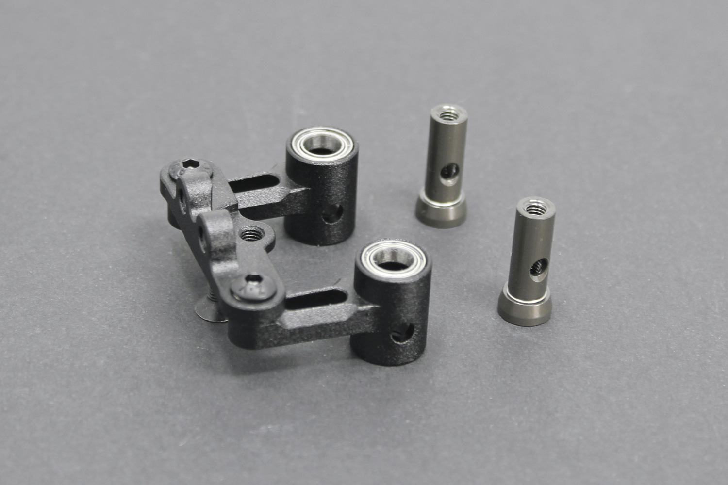
All four aluminium lower bulkheads are identical, with clear markings for the belt tension adjustments.
Each bulkhead is attached to the chassis with two 3x6mm screws – no pins or lugs.
Bulkheads are spaced 18mm apart.
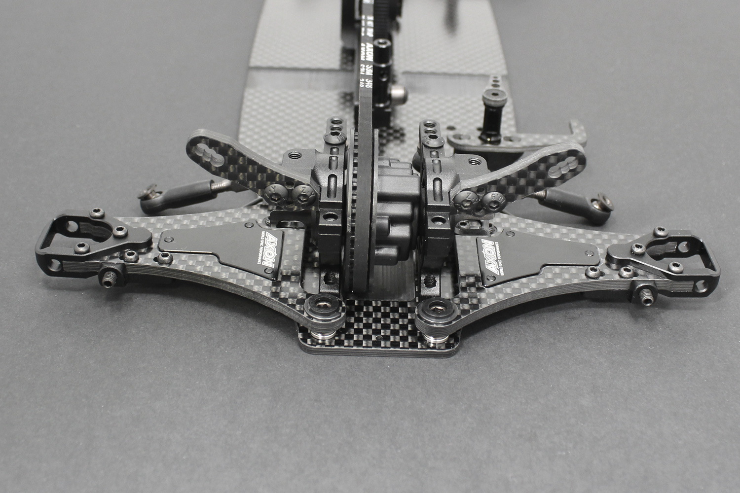
The rear diff now in the car, held down by the upper bulkheads, and you also get a good view of the rear towers. Everything sits very low.
Front spool with front upper bulkheads and towers. You can also see the front bulkhead stiffener made from 2.0mm carbon fibre.
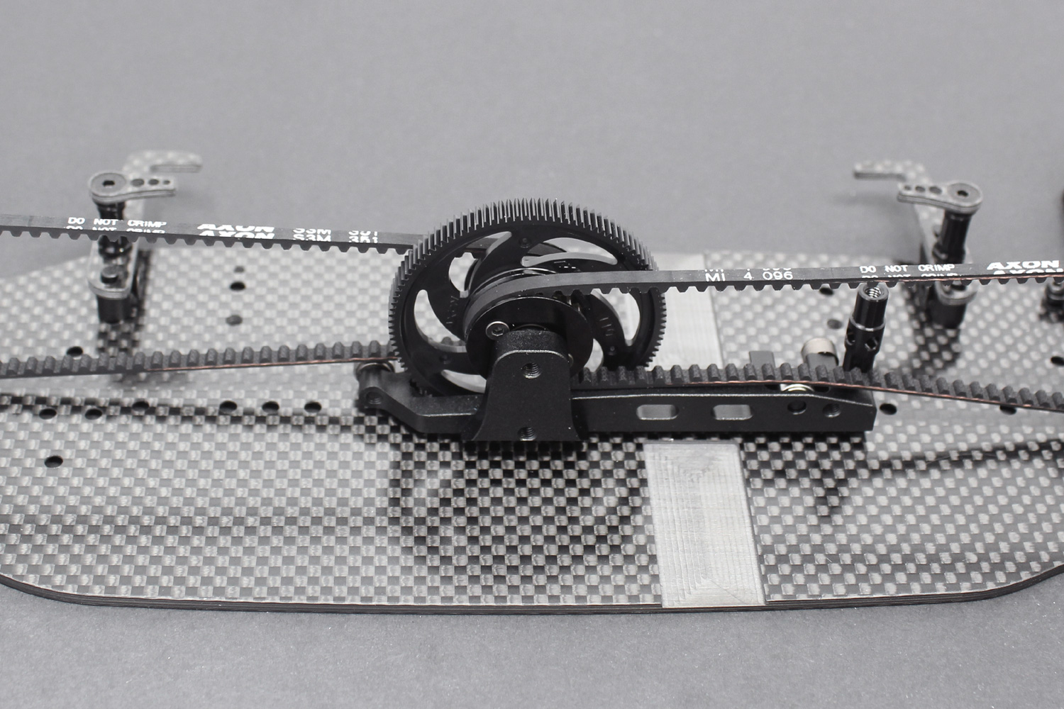
Motor mount and centre drive assembly mounted to the chassis, and you see how the belt is routed obove the motor mount with the help of the ball bearings. The whole assembly is very narrow. If my quick measurements are correct the motor mounts to the car 7.5mm from the centre line.
Axon branded belts are included, and while the front belt is 351mm long like most other mid-spur TC’s, the rear belt is 348mm. This obviously affects the axle positions, which then changes driveshaft angles. This is very much a conscious choice from Axon to change the behaviour of the car during acceleration and deceleration.
As you already saw on the motor mount photo earlier, there are lots of choices in terms of flex settings for the motor mount. This is the standard setup.
This photo also tells you that the included 110T spur is about the maximum size possible.
Rear body mount plate and body posts. This is mounted on top of the rear upper bulkheads where the bulkhead stiffener goes up front.
Some weight information for chassis and bulkheads etc.
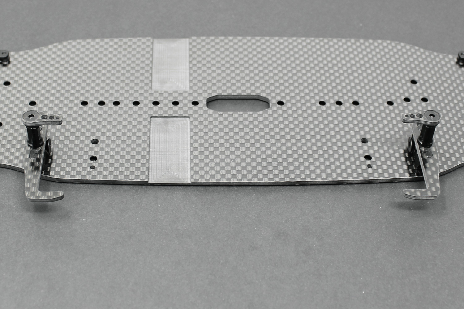
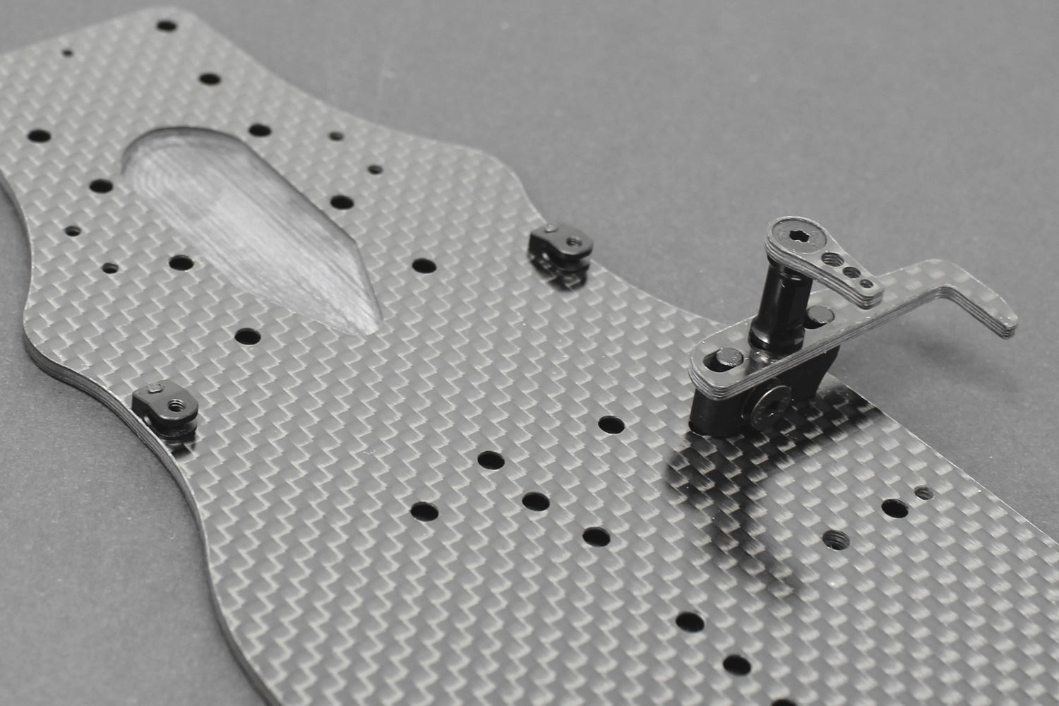
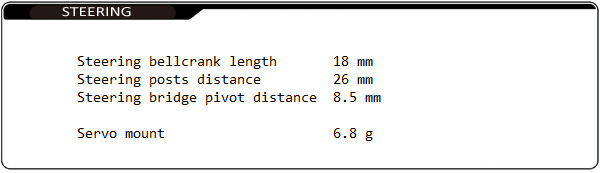
A conventional dual bellcrank seteering is used on the TC10/3. This consists of two identical alu steering arms, which use two 5x8mm bearings each. A steering bridge with pre-fitted bearings is mounted to the arms, and this assembly then goes onto two grey anodised steering posts. Thin shims are included for both the steering bridge and post screws/bearings.
To make it easy to securely mount, but also remove the steering system from the car, both the steering posts and arms have holes which line up. When the steering is in the car, just insert a pin or any tool here and you can easily remove the whole steering assembly. A simple but very welcome feature.
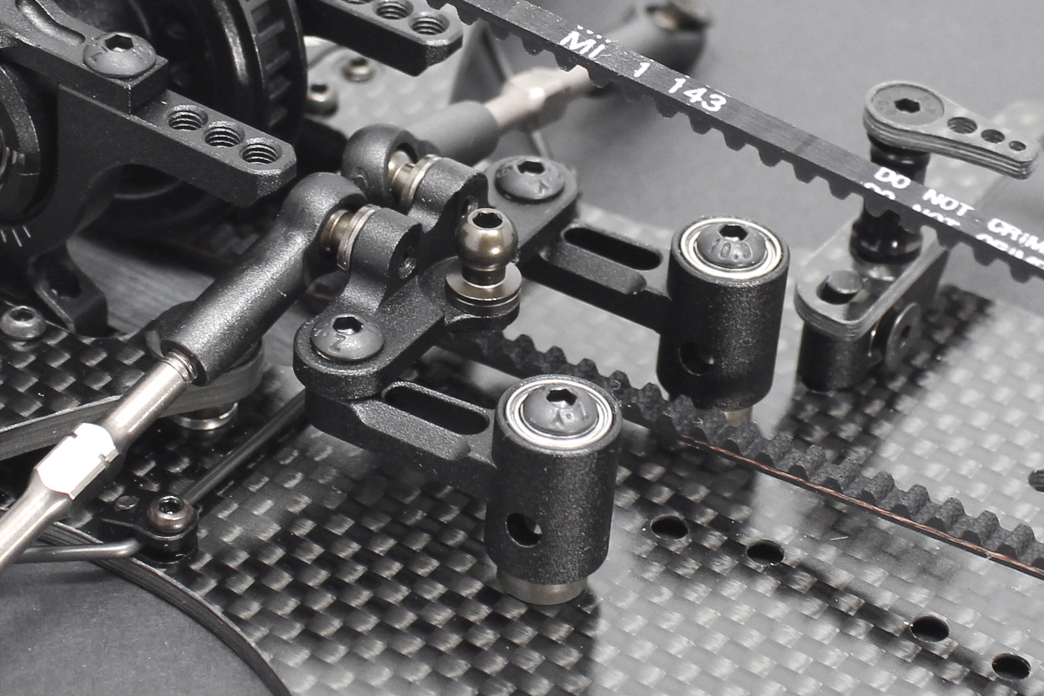
The steering bridge positions the steering links quite high to match the high position of the upright arms.
The steering so far feels very precise and with a minimum amount of play.
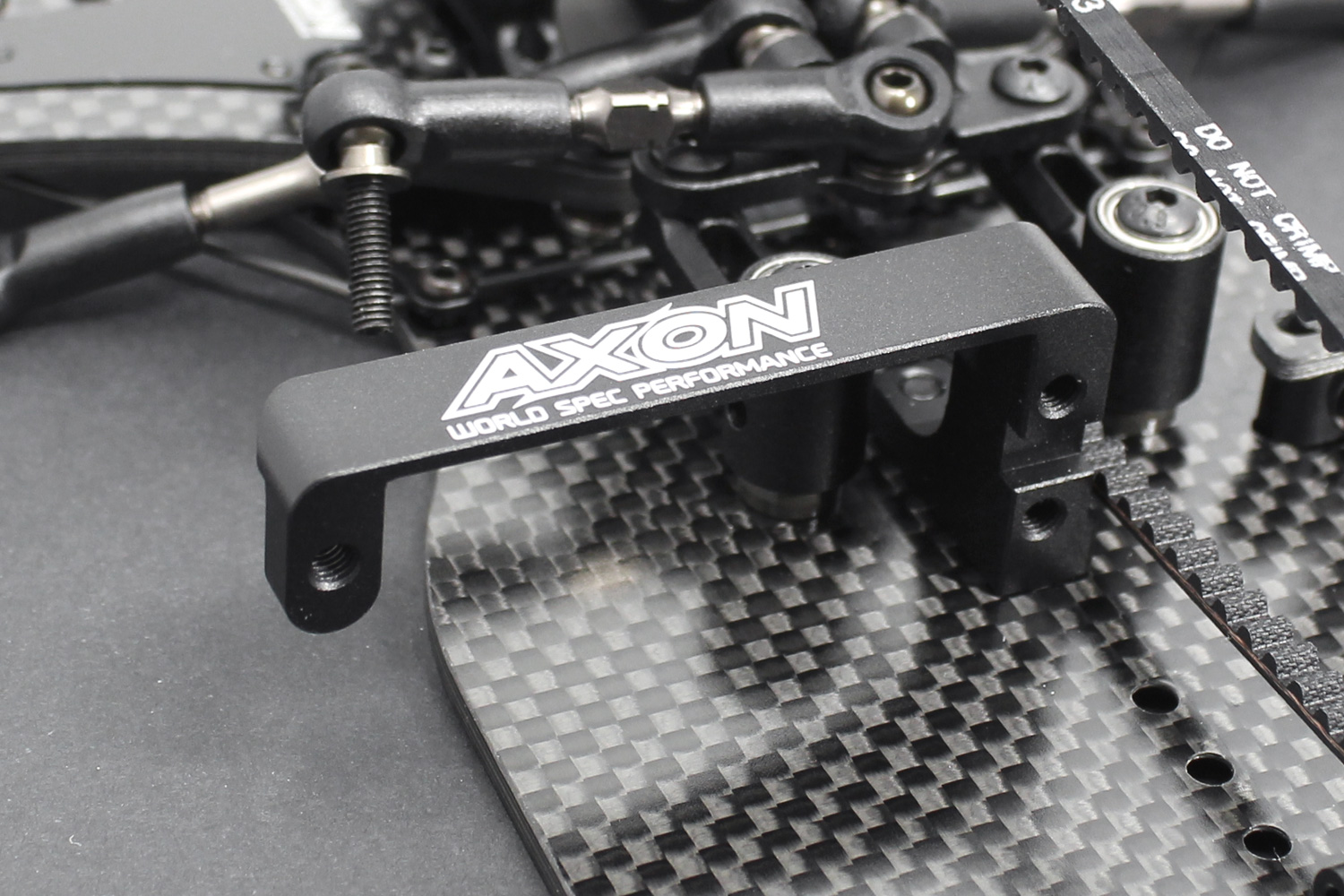
The floating servo holder looks super beautiful and is fairly light. It is secured to the chassis in with three screws in a slight forward position compared to the servo, with one of the screws offset from the other two
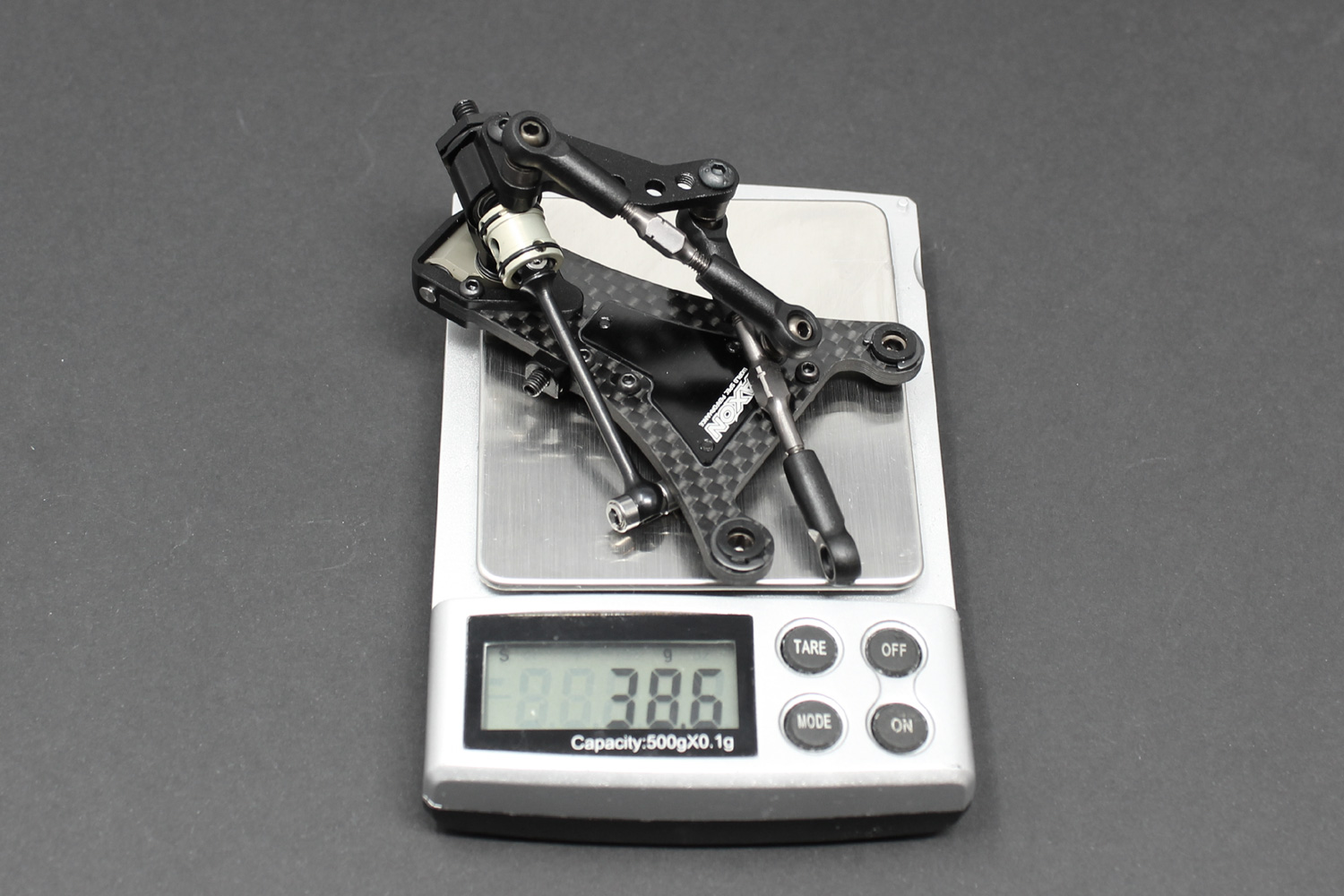
Some measurements on the steering components.
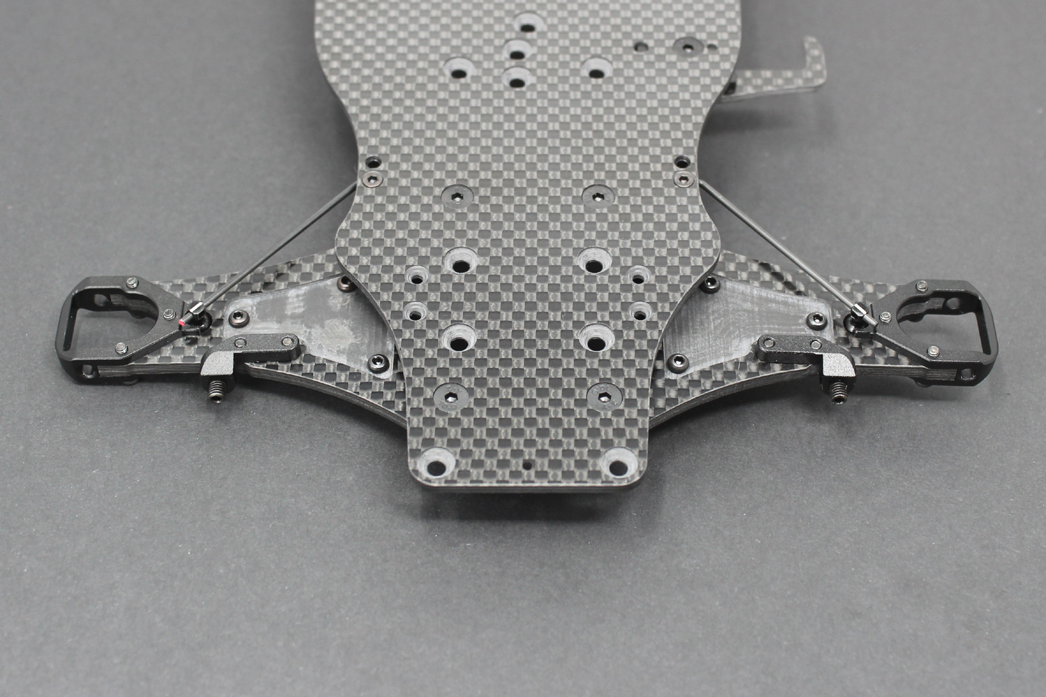
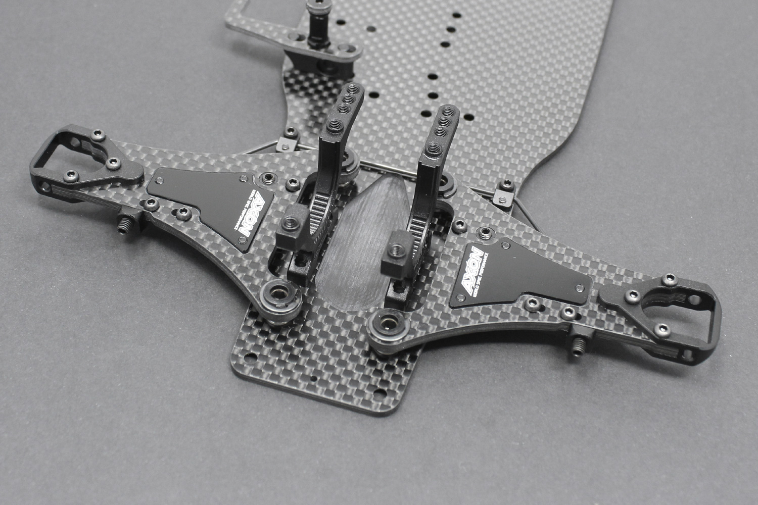
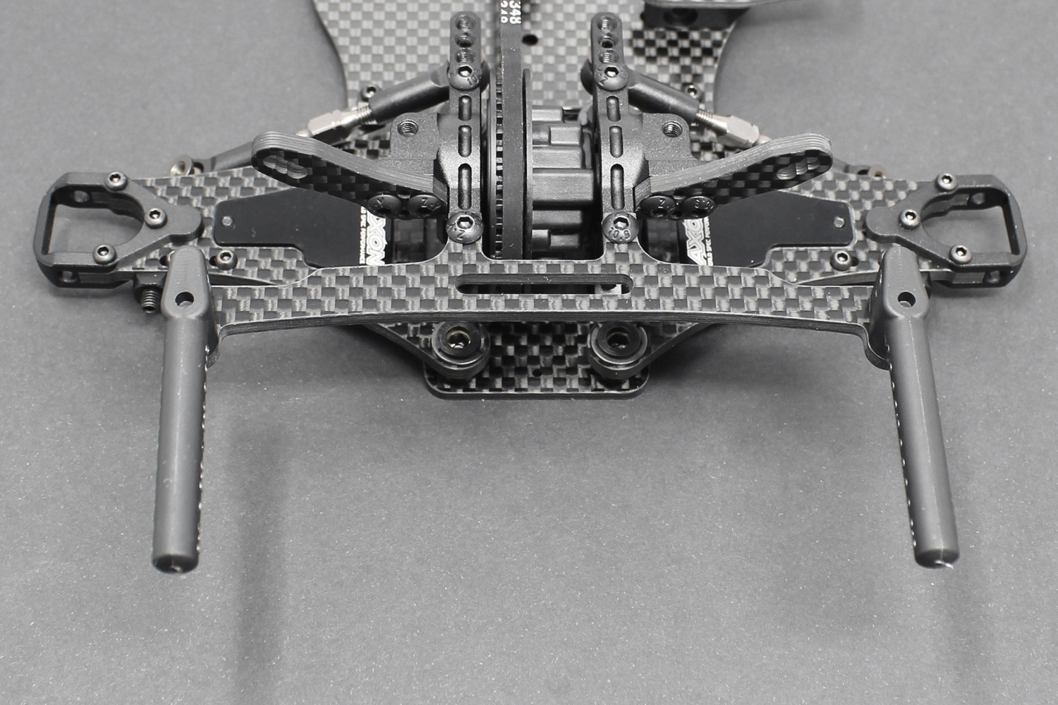
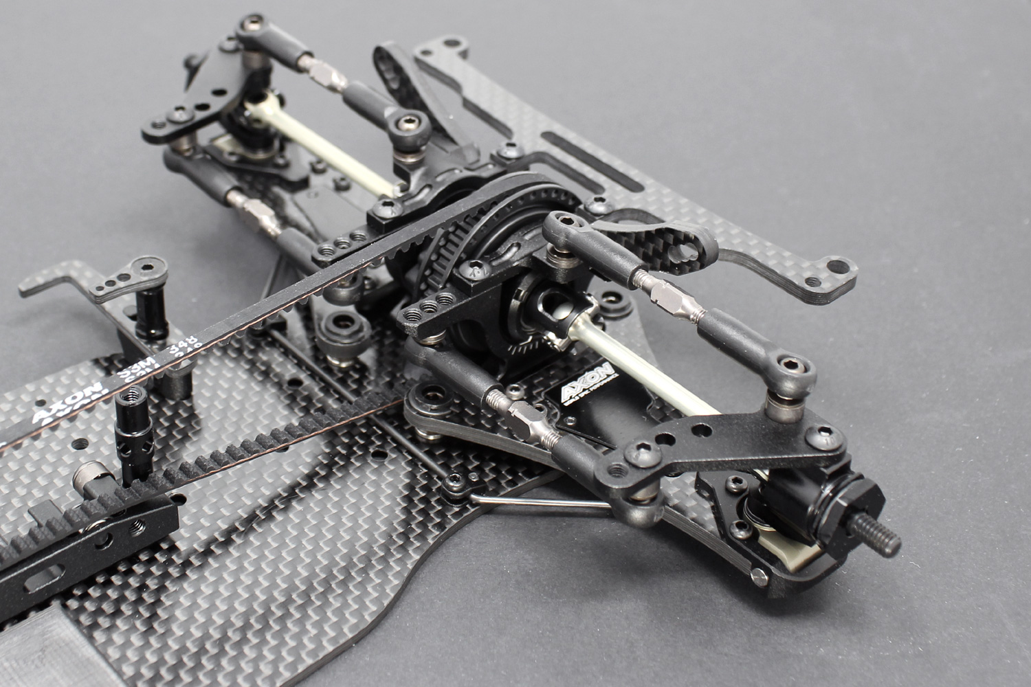
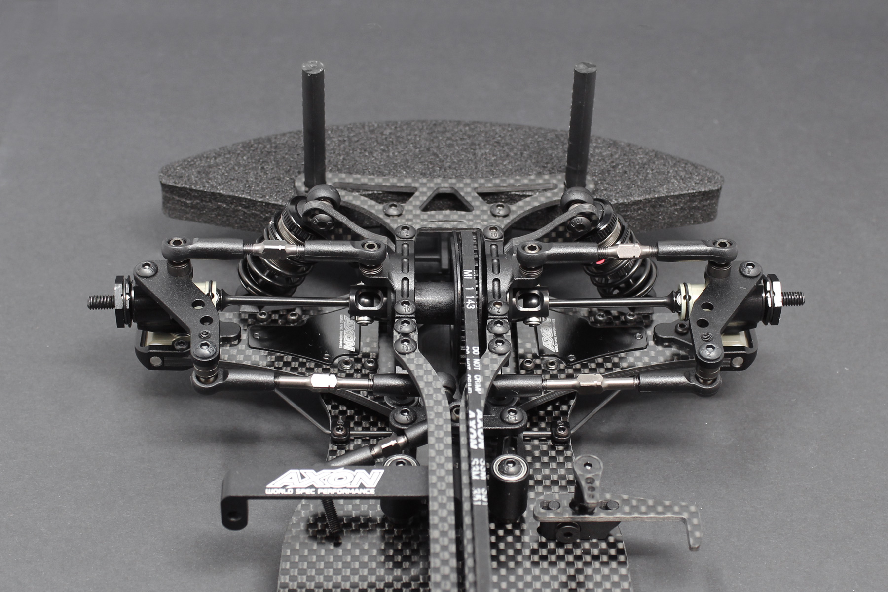
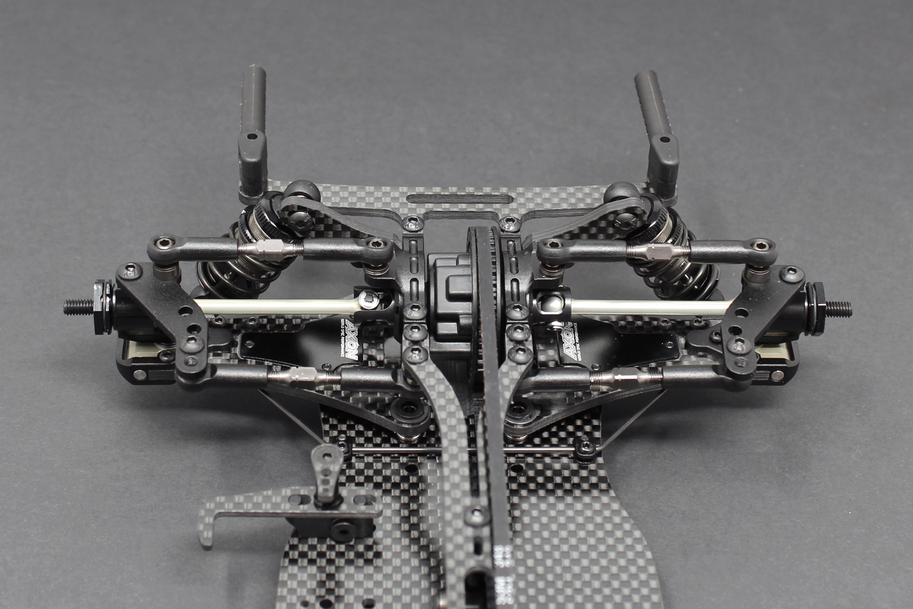
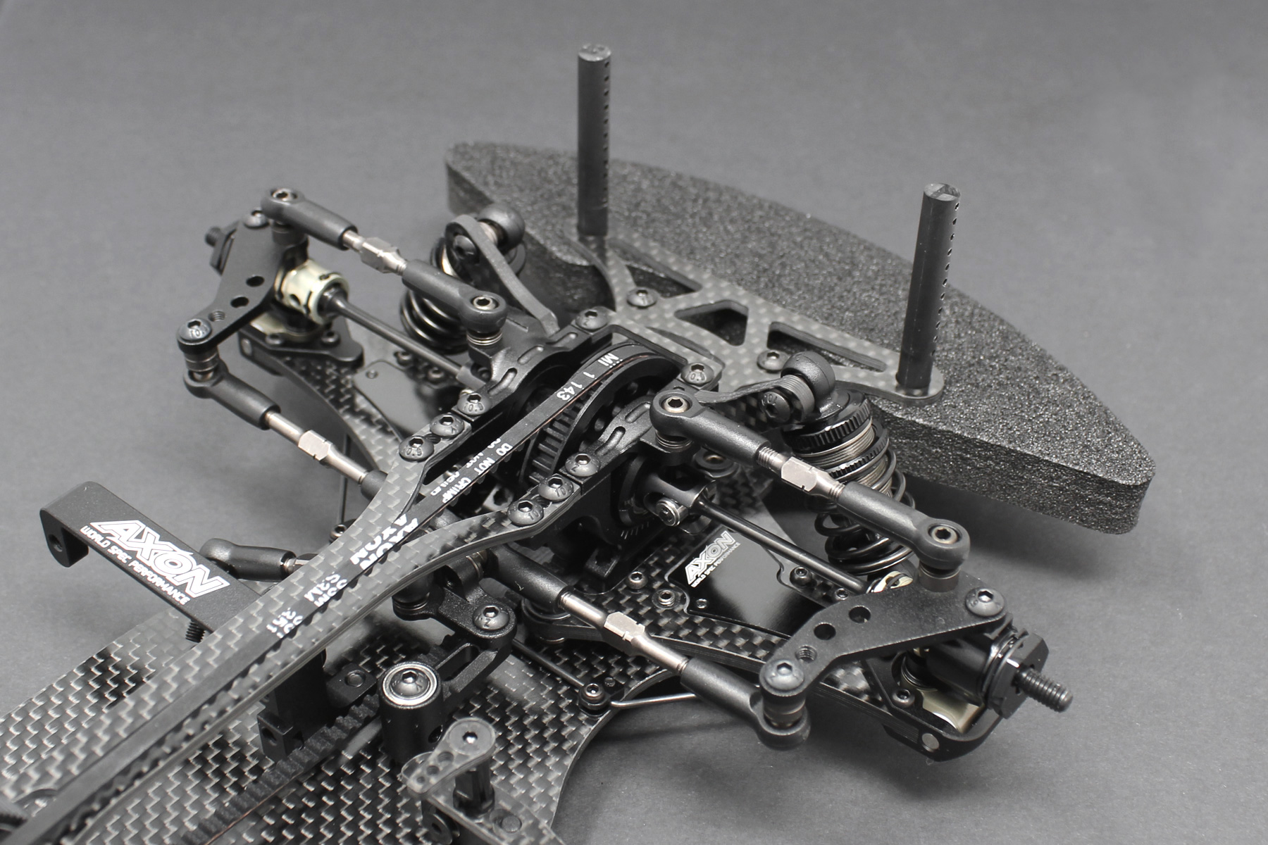
Finally the complete upright assembly is on the car so we can see what the suspension looks like.
Although the lower arms are long, they are not mounted as far inboard as on many other cars, but this is obviously due to the different geometry used with the outer hinge pins, where the outer pivots are much further outwards.
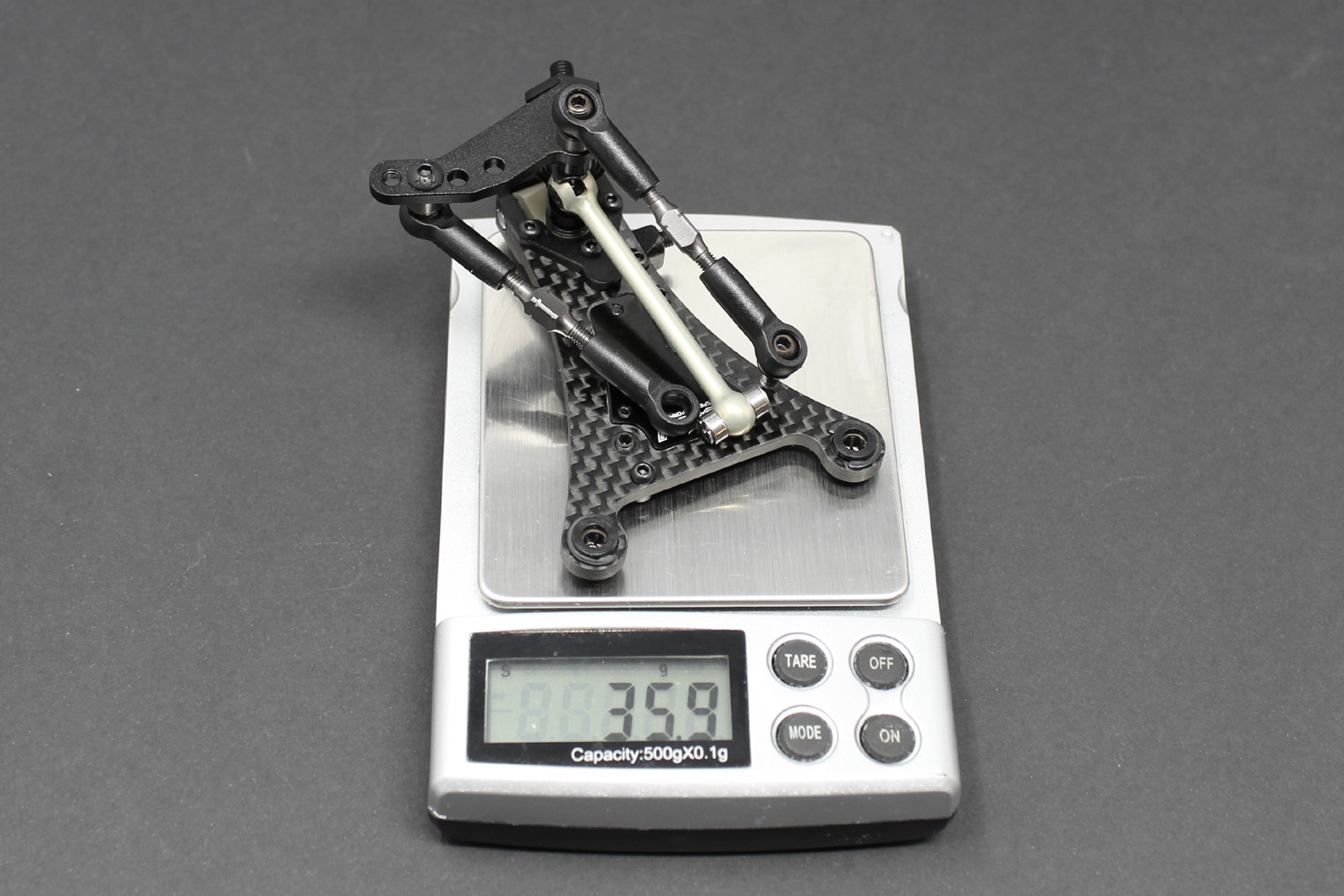
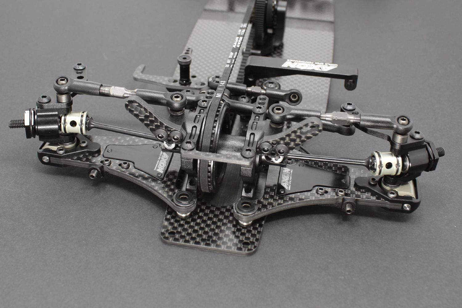
For reference, here are the weight of the complete suspension rear (above) and front (below).
If we compare this to when I built the Mugen MTC2, on that car these weights were 32.4g and 37.0g.
The front and rear upper arms both use 1.5mm spacers inside and 3.0mm outside.
Isolating out the play coming from the plastic pivot bushing on the inside of the arms which I mentioned earlier, there is just a small amount of play coming from the uprights and upper arms. Probably the right amount for a well working car in all conditions.
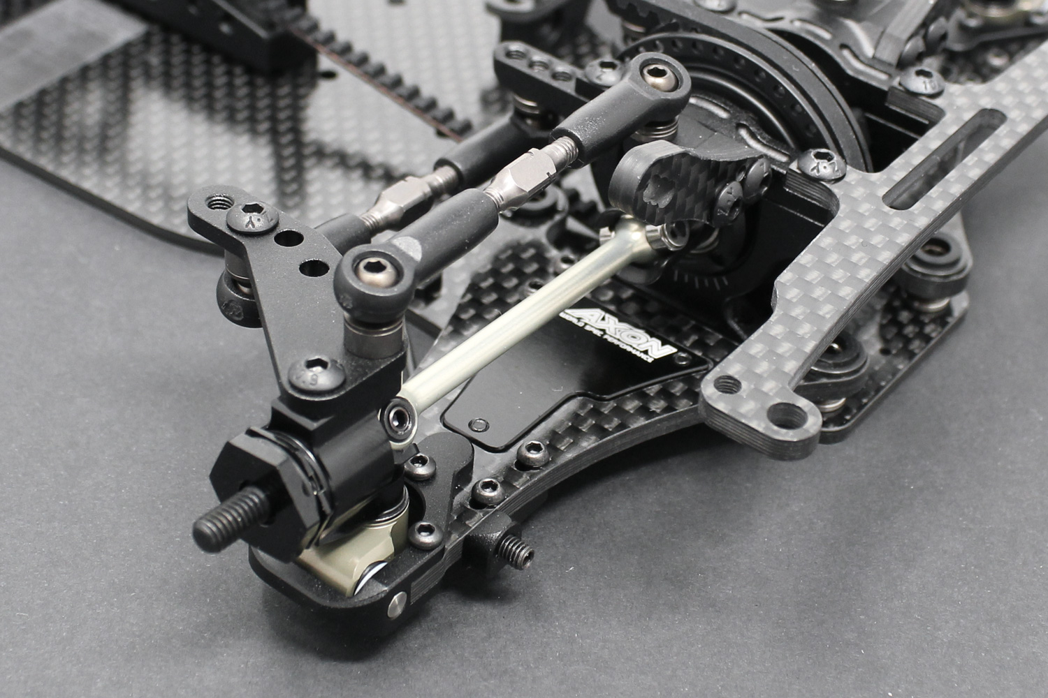
Special “teflon slider shims” are used between the arm and caster block, and you can see that in white in the image above.
One curious thing to note is that the TC10/3 does not include wheel nuts, but comes with wheel spacers (4 x 0.2mm and 4 x 0.3mm) to adjust track width.
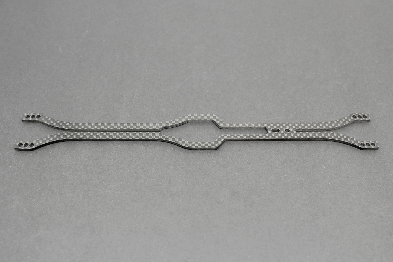
The upper deck is one-piece and symmetrical, and made from 2.25mm carbon fibre. A thinner 2.0mm thick upper deck is optionally available.
Fitting an upper deck with this design on a car layout like this is a bit tricky as you need to get the upper deck around the spur and under the belts, but once you find the right procedure it’s not too bad.
The upper deck is fixed with four 3x6mm screws in the front bulkheads, and the same for the rear, with one screw fixed to the motor mount “roll post”. Like this, the car still has a good amount of flex. If you want less, you can add screws to the motor mount, and if you want more you can remove the “roll post”screw, or alternatively get the thinner upper deck.
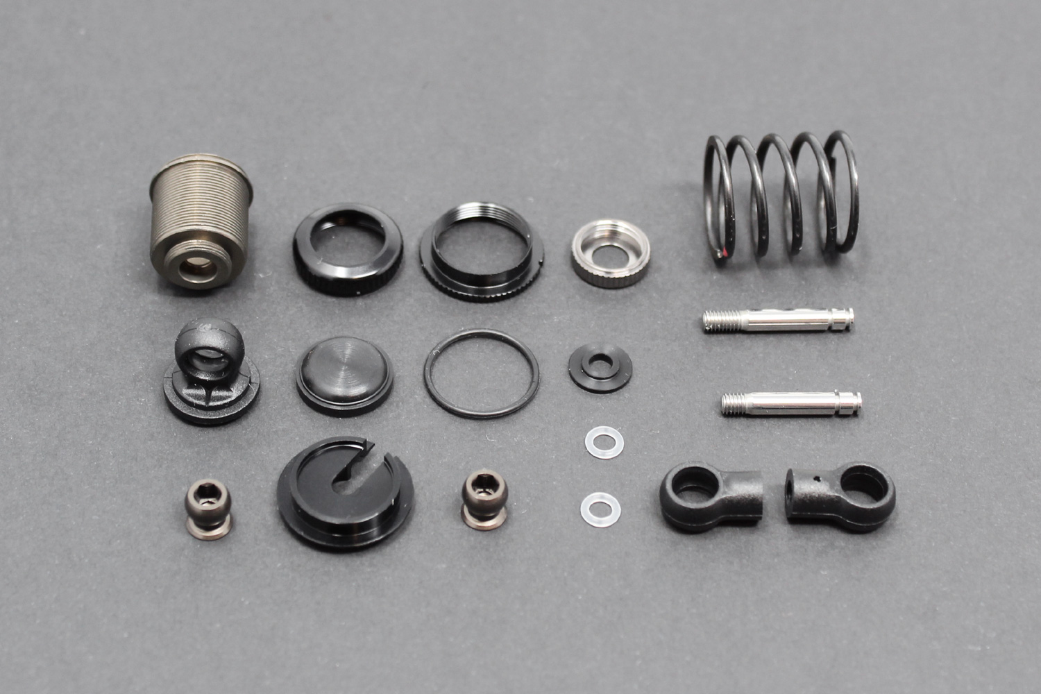
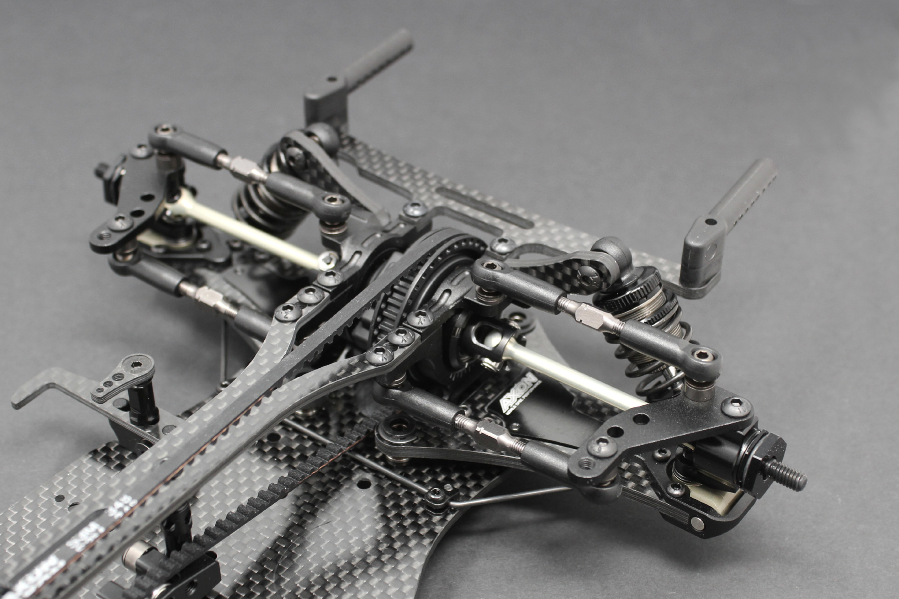
As we now move onto the last bits to assemble, it is time to build Axon’s new “High Big Bore Shock 4” which are the dampers included with the TC10/3. I already have experience of a couple of generations of Axon’s dampers, and they have always been experts in making really good ones.
The Gen 4 damper is now really short and it’s getting to the point where it’s abit finicky to build, as the parts are so small and low, with very short threaded areas. The damper cylinder is still fairly large, with length cut in other areas, and the damper is designed for use with the new shorter 18mm springs. The hex balls used are the same as on the lower arm, i.e. 6mm in the parts list but 5.8mm in reality.
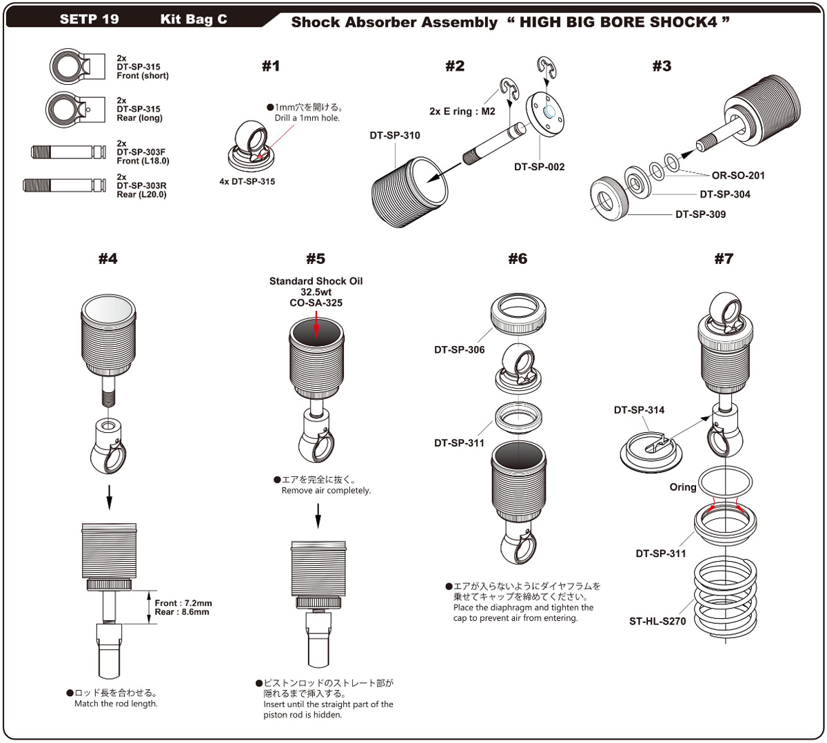
The damper comes with 4 hole pistons and Axon’s super soft bladders are used. However, the biggest update is the use of Axon’s new micro o-rings which according to the manufacturer will really improve the damper performance. There are two each of the micro o-rings in each damper.
The bladders still sit on top of, and not recessed into the cylinder like on some recent cars.
Again, no damper oil is included. The manual suggests 32.5wt.

Once built the dampers feel very smooth, and I’m convinced they should work well. They really give the impression of a well working damper, and this has always been super important for any well working car.
Axon’s new super short World Spec HLS-SS C2.7 (Red) springs are included front and rear. At the moment Axon offer 5 different springs in this range – C2.6, C2.65, C2.7, C2.75, C2.8.
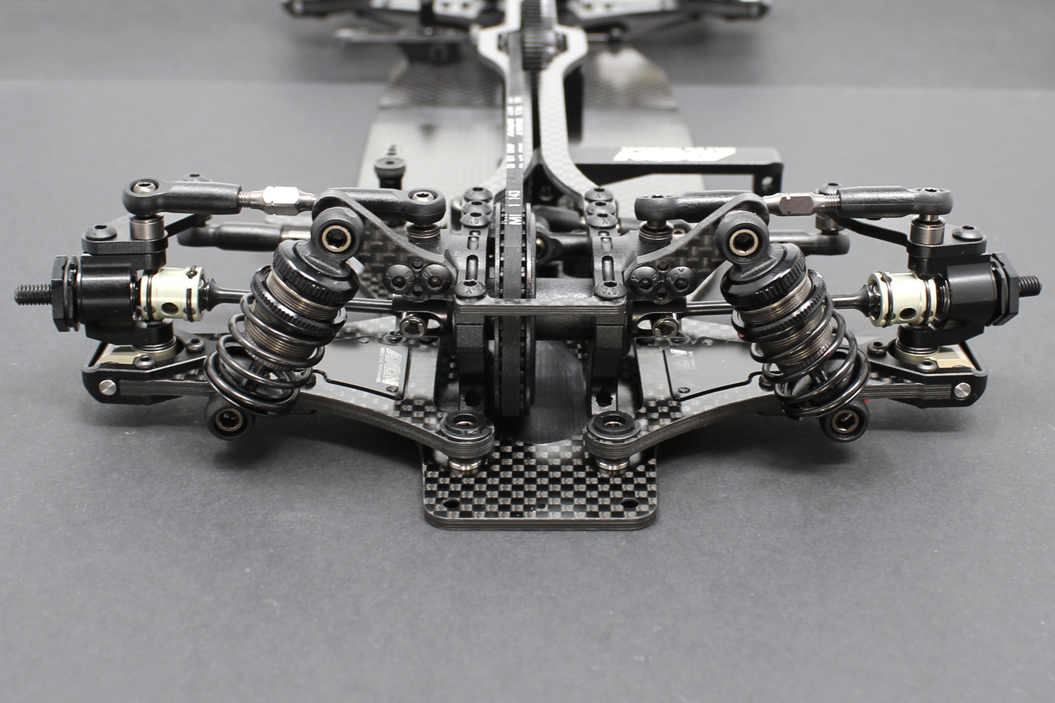
Front dampers are now mounted and the front suspension is complete.
Like mentioned earlier, a 3mm hex wrench is used for the hex balls in the damper.
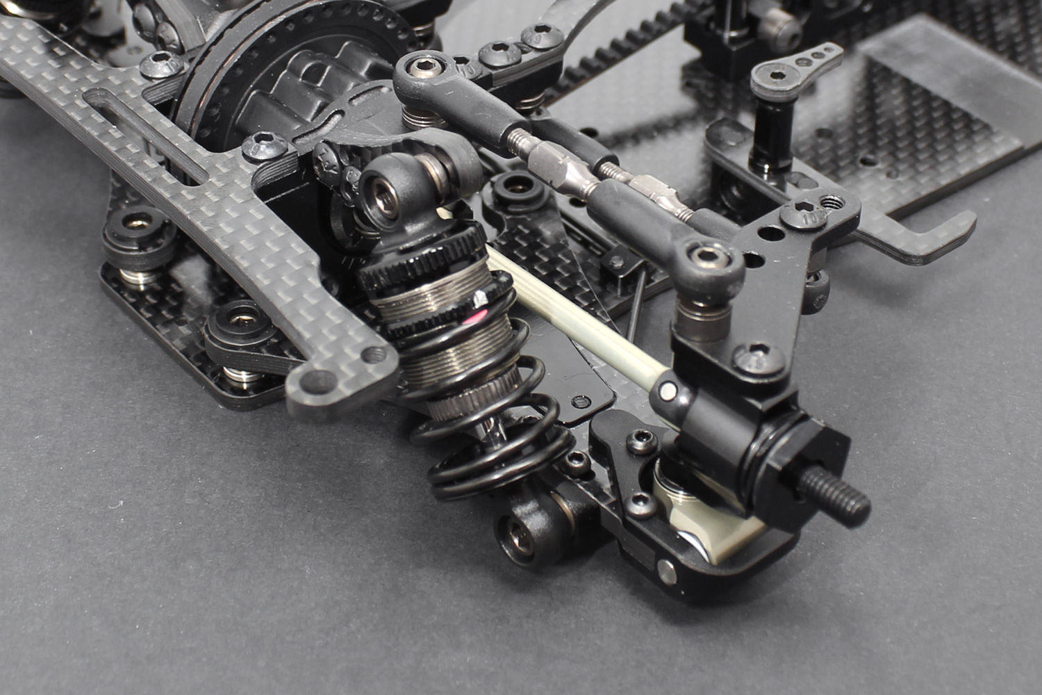
The slightly longer rear damper to go with the rear suspension geometry.
One millmeter spacers are used on the rear tower, while 1.5mm on the tower and 0.5mm on the arm is the default setting at the front.
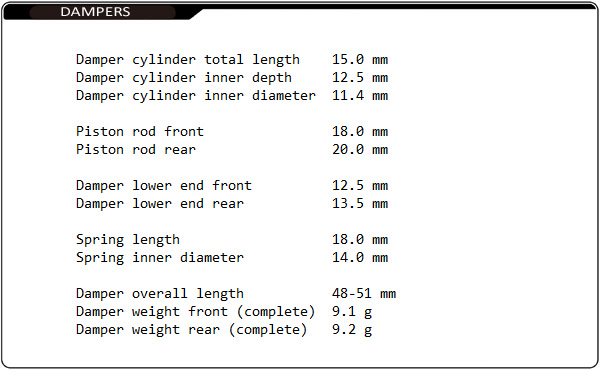
More exact damper specifications.
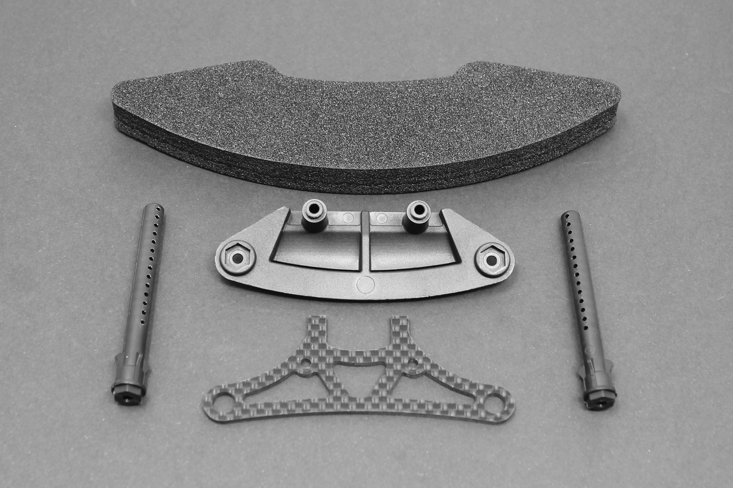
The plastic front bumper and body posts looks suspiciously like Yokomo parts, but who knows?
These are complemented by a foam bumper (thank god no ugly 3D printed stuff 🙂 ) and a 2.0mm thick carbon upper support. Two small plastic bushings are included with the bumper and these need to be fitted between the bumper posts and upper plate, even though the manual does not show this.
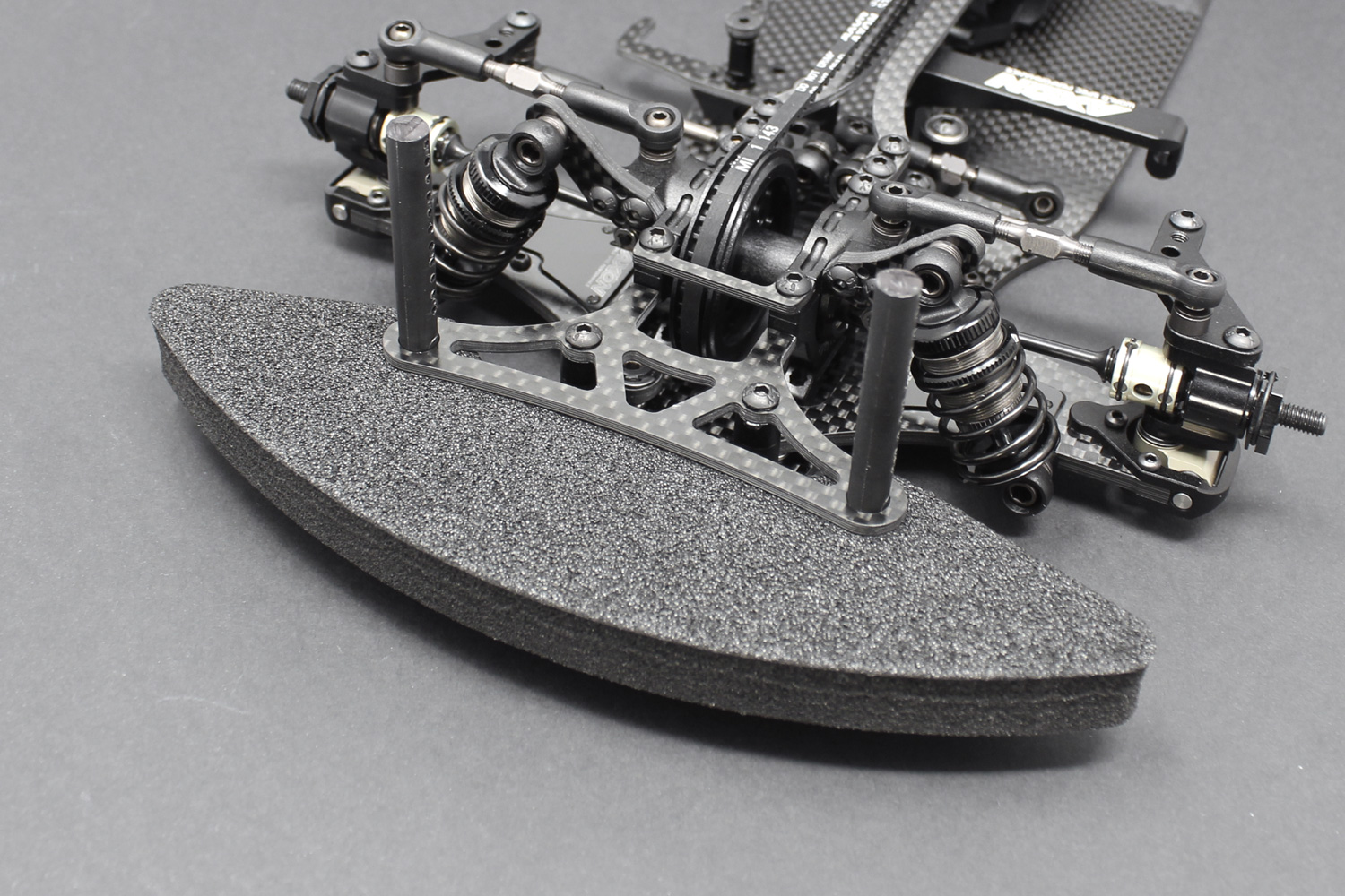
When using those bushings, the height of the upper brace is correct, so that its rear legs meet the front bulkheads for added protection.
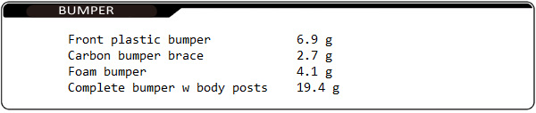
Bumper weight data above.
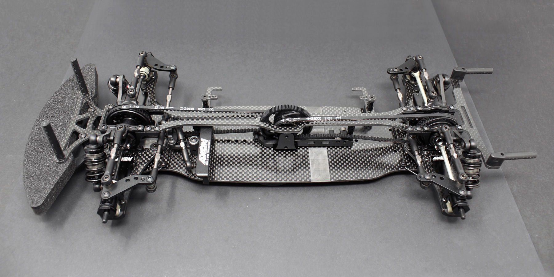
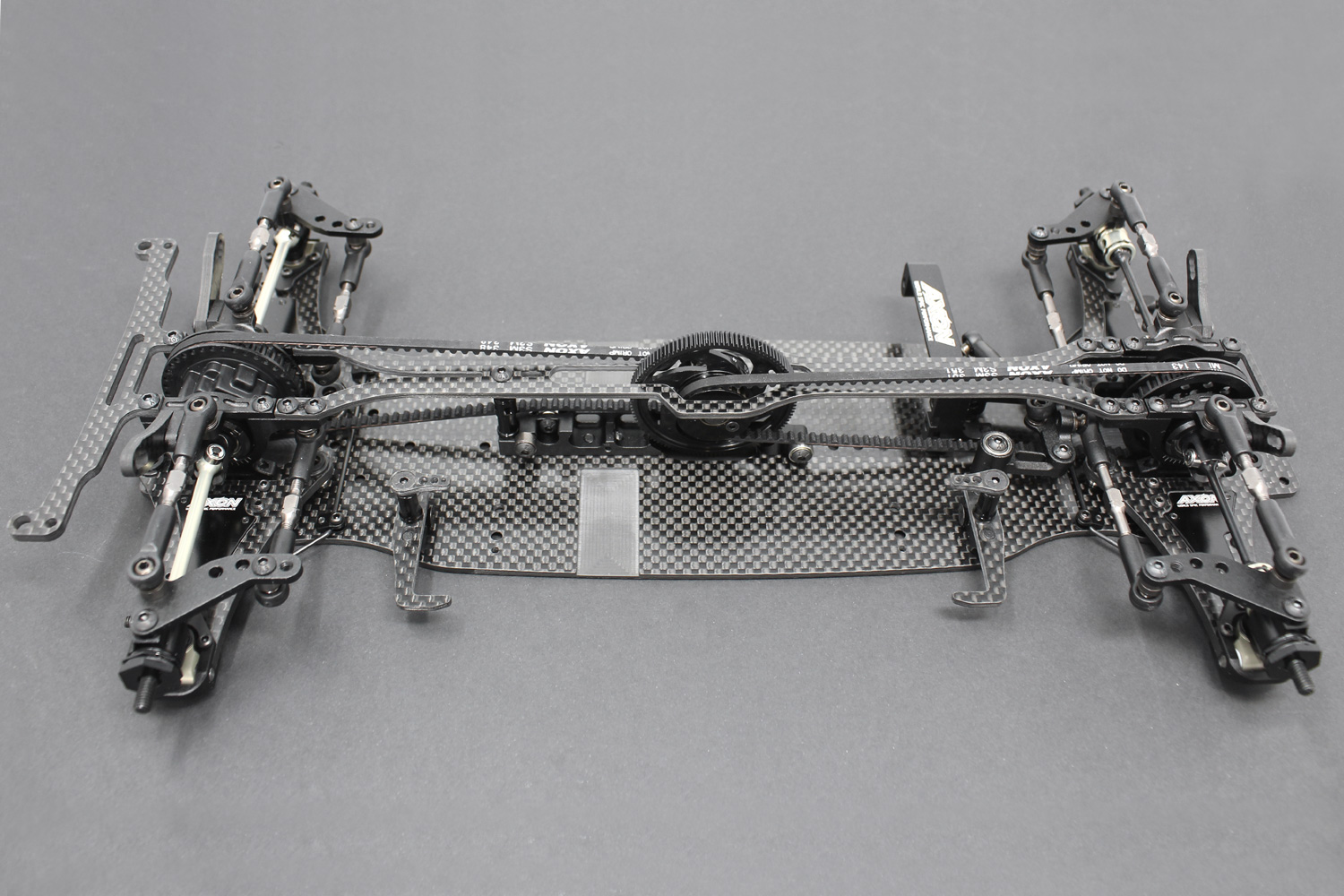
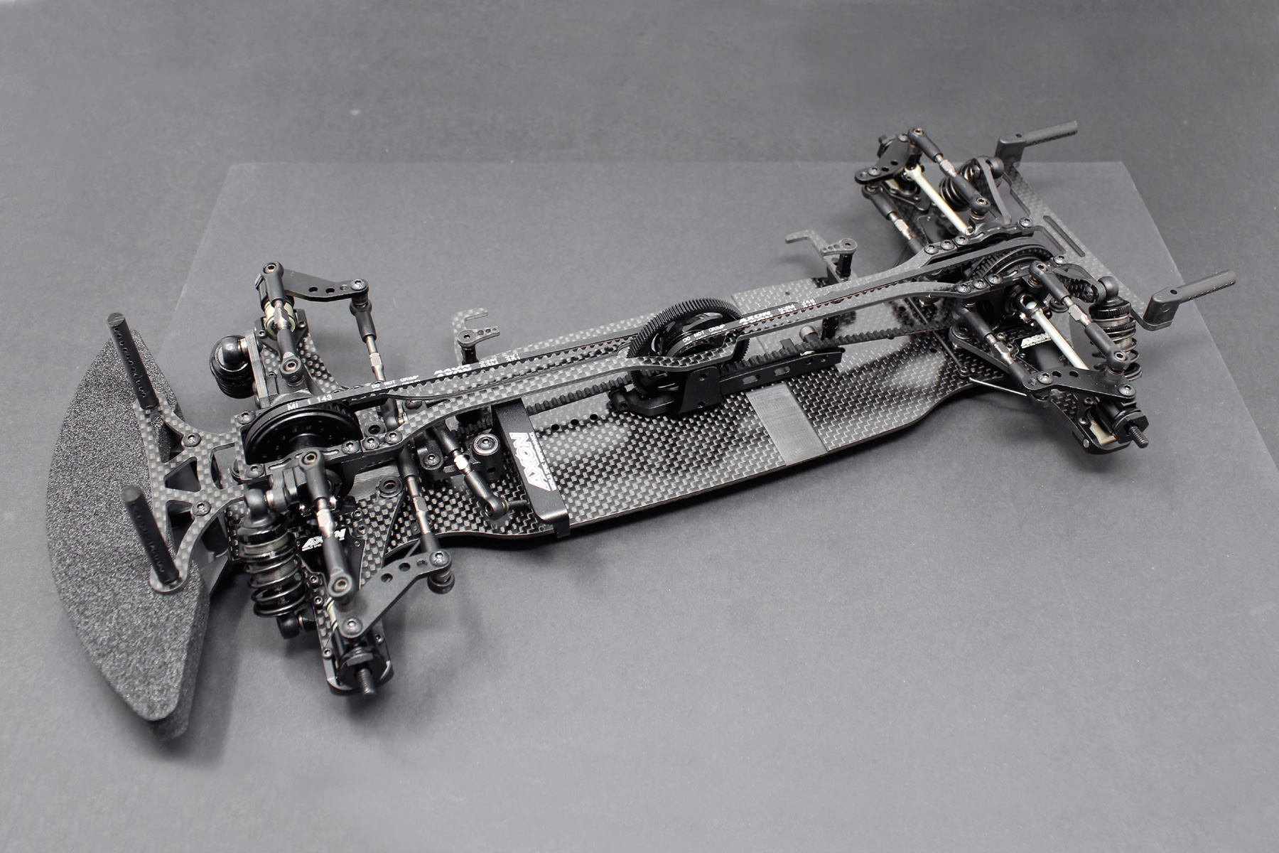
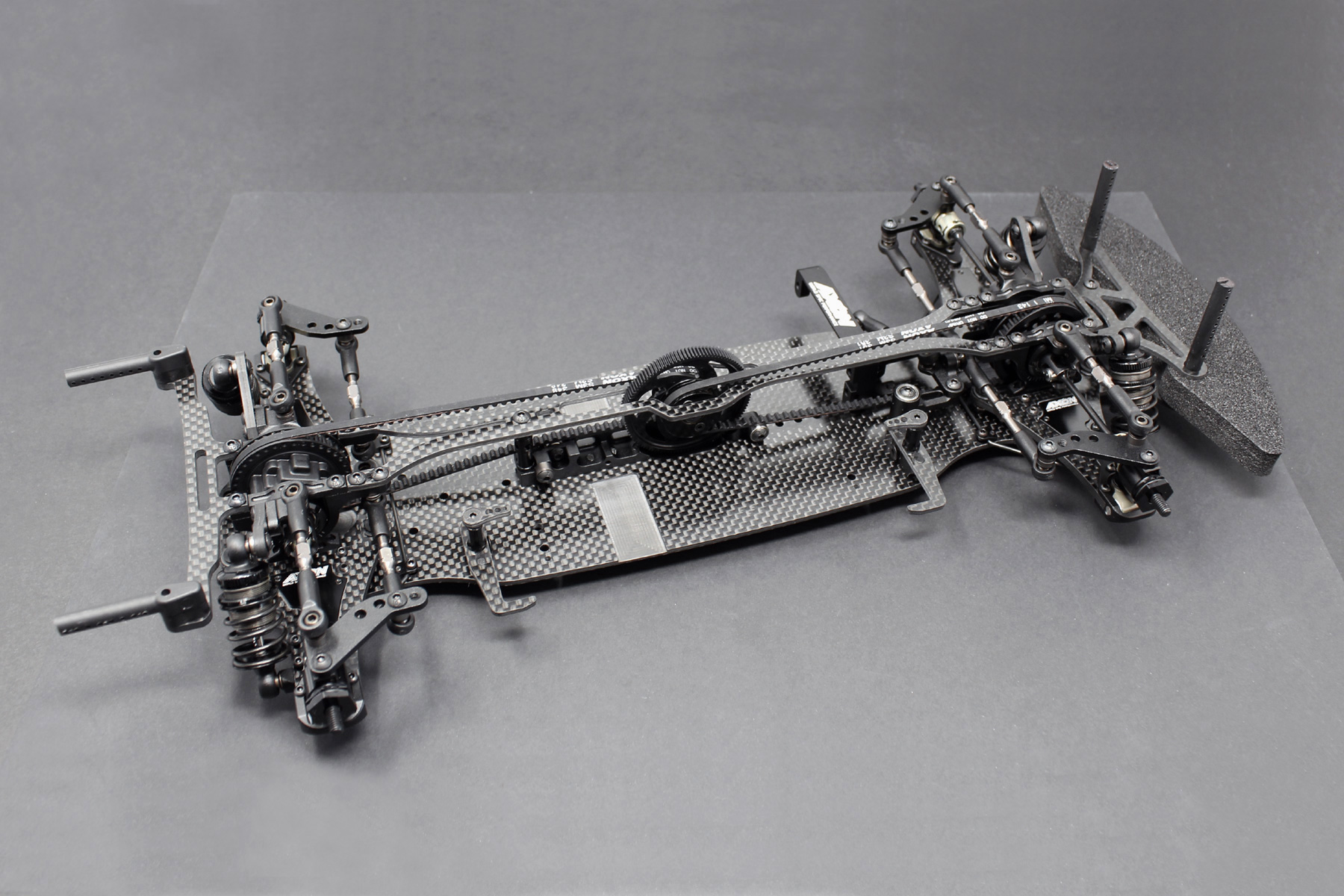
With the front bumper assembled and mounted to the car, the TC10/3 is complete, and this is what it looks like.
I had high expectations for this car, and for the most part the car built exactly as I had expected and the detail quality and finish lived up to my expectations. The car gives the impression of a product which is the result of a long period of development, with time and thought spent on every detail. This is also evident in many of the very simple but clever ideas incuded in the design.
Another impression is that it is a very slim design, with part dimensions and designs cut down close to the minimum in many cases. Also it really is a beautiful car in detail.
And race results have shown that Axon are at, or at least very close to the top of the TC racing scene currently. Initial customer reports from Japan (which has had the car for 1.5 months) were that the car seems very quick. I have no doubt that the car will work well once I can test it this summer, and it will be super interesting to try it.
There are of course still things to work on, and some question marks remain. The policy of no fluids, no printed manual and even no wheel nuts is a bit disappointing in a 700 EUR kit. There is also still no alu chassis available, although Axon have promised one will be made available. And like I mentioned at the start, the communication and information needs to be improved if they want this to become a worldwide success, and not only in Japan.
At the same time you get a very high spec pure racer kit, and one which should be quite enjoyable and simple to work on.
It’s now not long until the 2024 edition of the TITC, and it will be really interesting to see how competitive the Axon team is at this race as most top teams will be present. This is also a Worlds year, so throughout the year we will get a good read on the TC10/3’s performance at the highest level. No doubt there will also be some updates to the car due to Axon competing at this level.
Having now spent a bit of time checking the fully built car more closely I feel I have to again point out how good the TC10/3 feels, and how impressive that is for a first car kit. The only point which takes away from this is the play in the arms/arm bushings. It’s very very smooth car, for lack of a better word. And it will very interesting to see how this translates on track.
Overall a very welcome addition to the touring car market.
I hope you enjoyed this build and presentation of the Axon TC10/3. There will no doubt be some mistakes, which I will try correct when I see them, but please feel free to let me know if you see any. Thanks for reading! 🙏
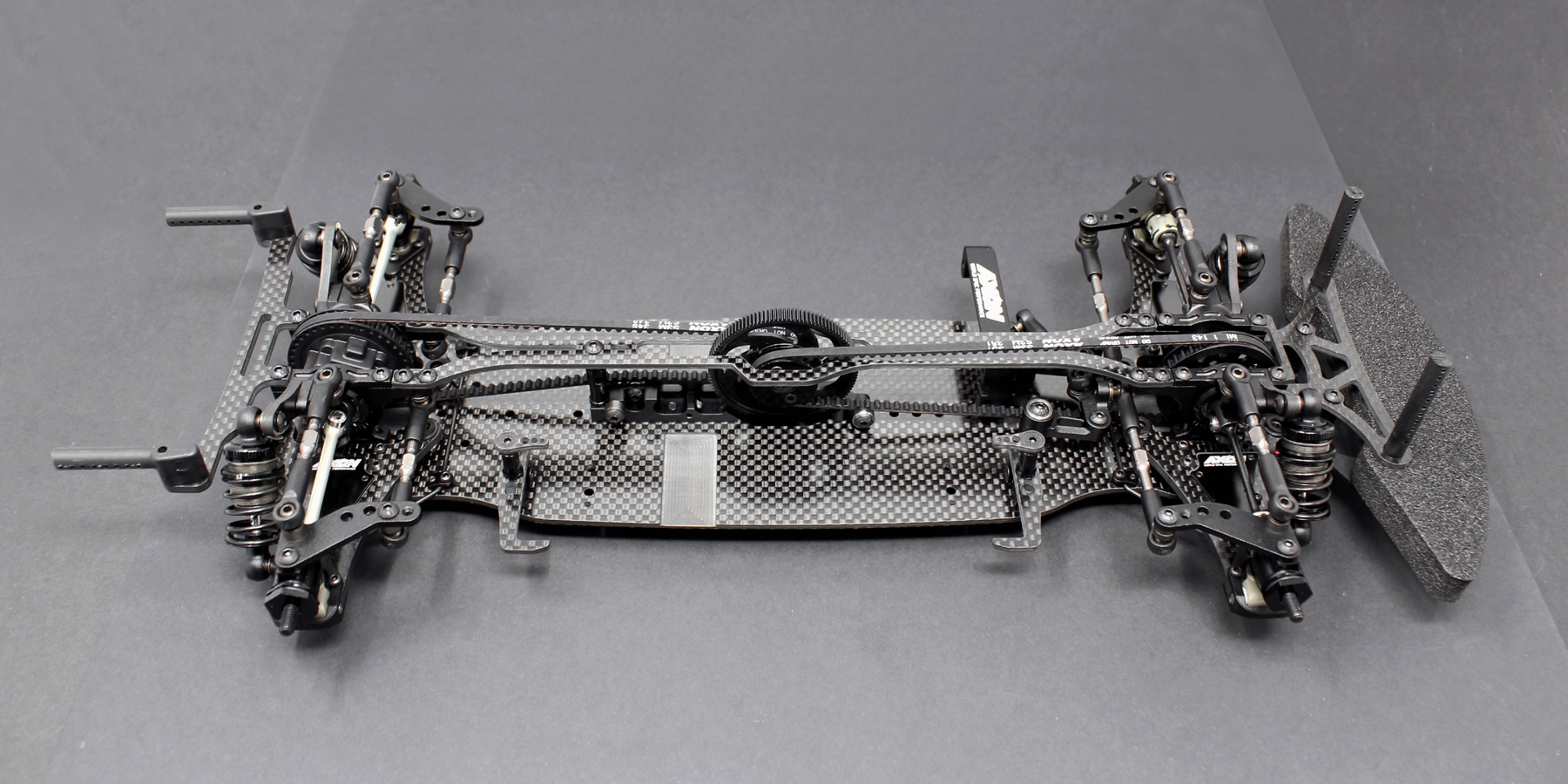
Overall the chassis completed and as seen here weighs 463 grams (MTC2 was 477g).
Finally I leave you with a couple of larger photos of the completed car.
Posted on February 13, 2024, in Uncategorized. Bookmark the permalink. 3 Comments.

Thanks for the in-depth presentation and your many remarks on build quality. The chassis seems nicely light compared to some competitors. I for sure am interested in the suspension weights (as you did before)… as well as the upper link length (to estimate camber gain). What’s your gut feeling of the robustness of the chassis? Do you see any parts flexing excessively, or is there even a risk for bending stuff (except the lower arms you mentioned). How easily did the ARBs work? Are they balanced L/R or do you need to twist the wire?
Thanks again. I’ve been looking forward to this, and your report didn’t disappoint!
Thanks! Weights are 35.9 (R) and 38.6 (F), I will add this info soon. Upper arms are ~48mm (c-c). It seems robust enogh for the most part, but I do suspect suspension arms will break around the pivot balls like I mentioned. Small alu part on suspension arms can always bend and That can of course be hard to notice, but even if the parts are small they seem well supported and good quality. Thought the ARBs were a bit of a pain to get in the super small arm mount end holes as the ball is already fixed in the arm. Although there is play and it’s very different, the bars were balanced without tweaking. Whether it will stay that way with use is another thing.
Pingback: TITC 2024 Summary + New Cars | BLOG KENTECH